Operation
49
Powerware
®
9150 User’s Guide
:
www.powerware.com
Isolated Alarm Relay Interface
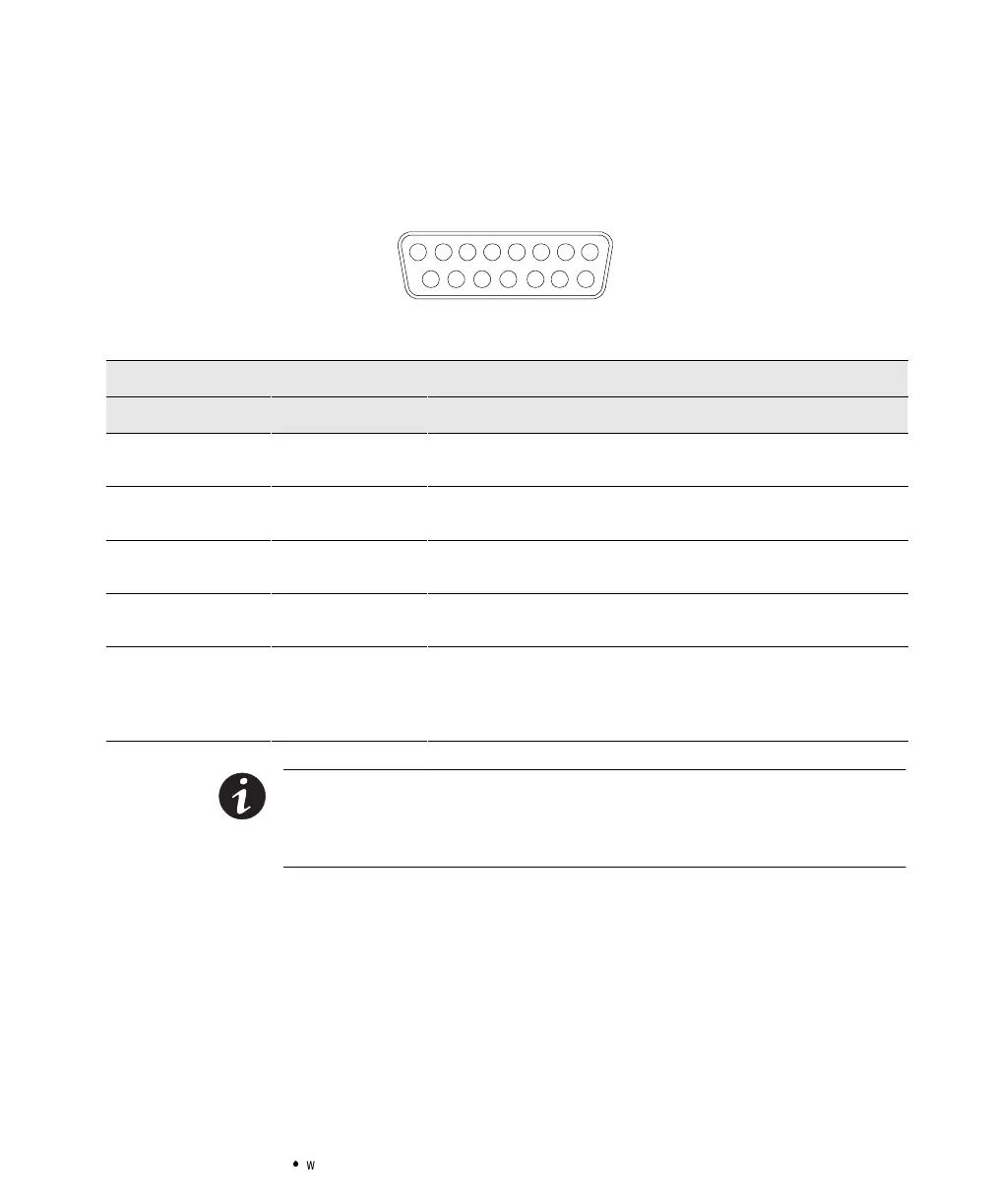
The isolated alarm relay interface uses a 15-pin, male, 42D-sub
connector.
12345678
9101112131415
Figure21.15-Pin SerialPort
Relay Interface of Powerware 9150
PinNo.Connection System State
Utility Failure 1-2Closed
1-3Closed
Line normal
Line failure
Low Battery 4-5Closed
4-6Closed
Battery normal
Battery low
UPS on Bypass 10 - 11 Closed
10 - 12 Closed
OnUPS
On Bypass
UPSOn or
UPSAlarm
7-9Closed
7-8Closed
UPSon
UPSalarm
UPS Shutdown
(in Battery Mode only)
13 - 15 Closed UPS shutdown when operating in Battery Mode. UPS can be shut down
by sending a hi-level signal (+5V to +15V) to Pin 15(+) and 14(-), or by
connecting Pin 15 to Pin 13. This signal must be present for a minimum
of 5 seconds.
NOTE The relaycontactsare ratedfor a maximum1A/30 Vac or0.2A/60 Vdc. All
relayoutputsare isolated fromthe other circuitsofthe UPS.Therelaycontactsmust
notbeconnectedto anyutility connectedcircuits.Reinforcedinsulationtothe utility is
required.