Operation
48
Powerware
®
9150 User’s Guide
:
www.powerware.com
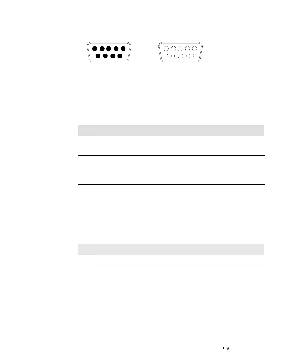
1234
786
5
9
Male Connector
(LanSafe III/FailSafe III or Modem)
5432
879
1
6
Female Connector
(OnliNet or ConnectUPS)
Figure 20. 9-Pin Serial Port
Use the female connector for a computer running OnliNet software or
for a ConnectUPS Adapter. The communication settingsare 19200 baud,
1 start bit, 8 data bits, No parity, and 1 stop bit. See the following table
for pin assignments.
RS-232Connection(Female)
Pin 1 Received data
Pin 2 Transmitted data
Pin 3 AC input failure, closing to Pin 4
Pin 4 Signal ground
Pin 5 Impending battery low, closing to Pin 4
Pin 8 +DC auxiliary power
Pin 9 Chassis ground
Use the male connector for a computer running LanSafe III/FailSafe III
software or for a modem connection. The communication settings are 1
start bit, 8 data bits, No parity, 1 stop bit, and XON/XOFF. The baud rate
is factory-set for 1200 baud and can be changed with a menu invoked by
sending
Control-C to the UPS. See the following table for pin assignments.
RS-232Connection(Male)
Pin 1 Data carrier detected
Pin 2 Received data
Pin 3 Transmitted data
Pin 4 Data terminal ready
Pin 5 Signal ground
Pin 7 Ready to send