SWITCH
PLATE INSTALLATION
AND
WIRING
To
installthe swilch
plate,
lollowtheoutlined
procedures
and
refer to Figure 3.
1.
Select
the suitable location
(bulkhead,
console,
etc.). Make sure lhere is enough room behind for
the entire switch and wires.
Cut a hole 1-3i/4' high and
1' wkle.
Applyalhin bead
of silicone sealeraroundlhe
edge
of the
switch mounting
plate
and attach the
plate
using
the four #8 round head
wood
screws.
CAUTION
N€ver attach th6
circuit brcaker
to
the
battery
ground
terminal
(negative
C)
post).
4- Attach the circuil breakertothe
positive
(+)
side of
the
battery.
5. Measure
and cut the reouired red and
bhck wire
lengths to connect lhe battery to the switch.
6. Crimp the small
(316)
ring terminal to one end of
the red wire and a female disconnect to lhe other
end.
7. Crimp the large
(5/16)
ring terminal
to one end o{
the black
wire and a female disconnect
to the other
eno.
8. Attach lhe ring terminal on the r€d wire
to the
unused
oost
on the circuit breaker usinq a
nut.
9.
Connect the female
disconnect on the rsd
wire to
Terminal
'D'
on lhe back of the switch.
minal
(positive
(+) post).
10. Connect
the ring lerminal on the black wire
to the
n€gative (-)
battery lerminal
post.
11. Connectthe
fernale disconnecl
on the black wireto
Terminal
'C'
on the back
of the switch.
12. Measure and cut
the required red
and black wire
lengrths lo connect
the windlass
lo the switch.
13. Crimp
a fernale disconnect
to one end of both
red
and black wires.
14. Connecl the
female disconnect
on the
rod wire to
Terminal
'A'
on the back
of the switch.
15. Attach
the red wire lo
the red motor lead
on the
windlass using
a butt conneclor.
16. Connectthe
fernale disconnect
onlhe black
wirelo
Terminal
'B'
on the back
of the switch.
17, Attachthe
blackwiretothe
black motorleadon
the
windlass
using
a butt connect.
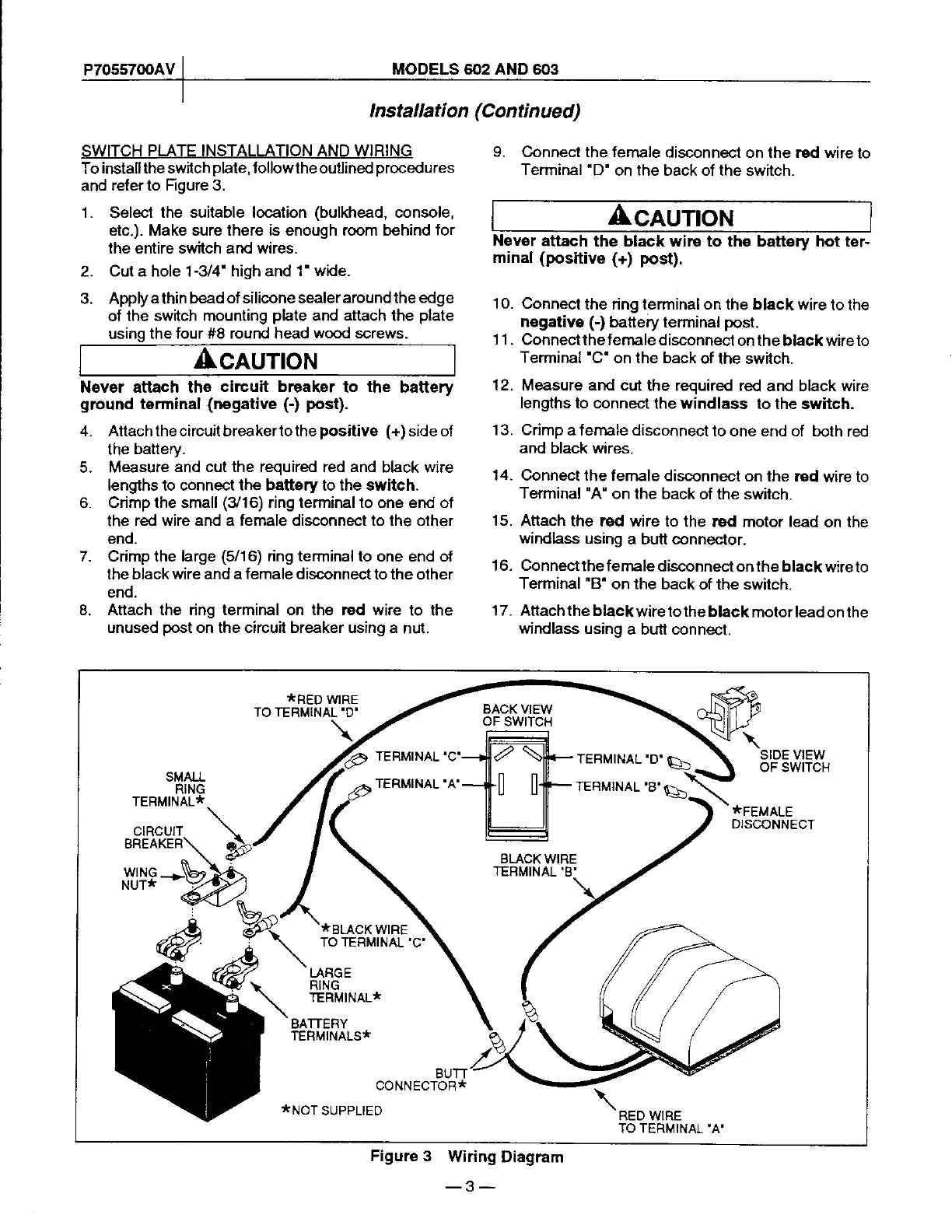
*RED
WIRE
TERMINAL'D'
\
BACK VIEW
oF
swtTcH
TERMINAL'C'
TERMINAL'A'
TERMTNAL'D'E)
SIDE VIEW
oF swtTcH
SMALL
RING
TERMINAL'
*FEMALE
DIS@NNECT
CIRCUIT
BREAKER
WNG
NUT*
*BLACK
WIRE
TO TERMINAL
'C'
LARGE
RING
TERMINAL*
BATTERY
TERMINALS*
BUTT
coNNEcToR*
:tNOT
SUPPLIED
RED WRE
TO TERMINAL'A'
Figure 3
Wiring
Diagram
-3-