EasyManua.ls Logo

Powrmatic CA-G series User Manual

Powrmatic CA-G series
16 pages
To Next Page IconTo Next Page
Page #1 background imageLoading...
Page #1 background image
Supplied By www.heating spares.co Tel. 0161 620 6677
Installation and Servicing
Instructions
The CA-G Range
W ARNING: THIS APPLIANCE MUST BE EARTHED
HEATING DIVISION
Winterhay Lane
Ilminster, Somerset TA19 9PQ
Tel: 01460 53535 Fax: 01460 52341
BSI Registered Firm
FM 414
Ind. & Comm. Air Heaters;
Air Moving Equipment;
Flues & Chimneys; Natural
Smoke & Heat Ventilators;
Powered Supply & Extract
Fans & Systems.
CA G Issue 6 January 1998
Every effort is made to ensure accuracy at time of going to press. However as part of our policy of continual product improvement, we reserve the right to alter specifications without prior notice.
CE
Question and Answer IconNeed help?

Do you have a question about the Powrmatic CA-G series and is the answer not in the manual?

Powrmatic CA-G series Specifications

General IconGeneral
ModelCA-G series
CategoryGas Heater
DimensionsVaries by model
WeightVaries by model
Voltage120V
AmperageVaries by model
Fuel TypeNatural Gas / Propane
ControlThermostat
VentingVented

Summary

3. General Requirements

3.4 Flue System

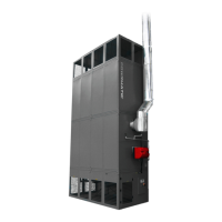
Requirements for flue system design, materials, and installation to prevent condensation.

3.5 Air Supply

Specifies minimum free area requirements for air vents based on heat input.

4. Installation of Air Heater(s)

4.3 Connection of Air Heater(s) to Flue System

Guidance on flue system connections, pipe sizes, and resistance limitations.

4.5 Gas Connection

Requirements for gas supply connection, servicing valves, and pipe support.

4.6 Electrical Connections

Instructions for final electrical connections, isolation, and cable sizing.

5. Air Distribution System

6. Commissioning & Testing

6.4.1 Gas Controls Assembly - Soundness Check

Steps to check the soundness of gas safety shut-off valves.

6.4.2 Sequence Check

Verifying the correct operational sequence of the burner and fan.

6.4.3 Final Adjustment

Procedures for final adjustment of gas pressure and CO2 content.

6.4.3.1 CA-G 100 - 300 Final Adjustment

Specific final adjustment steps for CA-G 100-300 models.

6.4.3.2 CA-G 400 - 2000 Final Adjustment

Specific final adjustment steps for CA-G 400-2000 models.

6.4.4 Final Soundness Test

Performing a final test on gas control assembly joints for soundness.

6.4.5 Flame Safeguard

Testing the flame safeguard system by closing the gas service valve.

7. Servicing

7.5 Replacement of Faulty Components

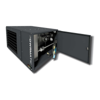
Procedures for replacing various components.

7.5.2 Gas Controls Assembly

Procedures for replacing gas control assemblies.

7.5.2.1 CA-G 100, 150

Steps to replace gas valve coil and block valve assembly.
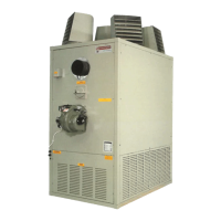
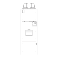
9. Fault Finding

Related product manuals