Do you have a question about the Powrmatic TE41 and is the answer not in the manual?
Provides detailed S.I. unit measurements for TE41 and TE61 models.
Lists relevant regulations, publications, and standards for safe installation.
Covers site selection, operating conditions, and required clearances for installation and servicing.
Details requirements for service pipes, meters, installation pipes, and boosted supplies.
Provides recommendations for flue system design, materials, and installation to prevent condensation.
Outlines requirements for air supply, including vent size and placement, for optimal heater operation.
Emphasizes proper air throw, return air path, and avoiding contamination for efficient operation.
Covers wiring requirements, voltage, frequency, and isolation provisions for safe electrical connection.
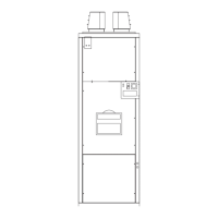
Pre-installation checks, site requirements, and minimum clearances for installation and servicing.
Specifies that installation must be by authorized personnel on a suitable noncombustible floor.
Details flue connection, pipe sizing, height requirements, and resistance limits for safe operation.
Addresses minimizing condensation in the flue and providing drainage if necessary.
Outlines the need for a servicing valve and secure gas pipework connection.
Explains connecting the mains supply, external controls, and ensuring adequate cable sizing.
Emphasizes that electrical safety checks must be performed by a qualified person.
Details inspection, testing for soundness, and purging of the gas installation according to regulations.
Instructions for checking and correcting fan rotation direction for proper airflow.
Step-by-step procedure for igniting the air heater and establishing the main flame.
Guidance on instructing the user, setting controls, and emphasizing annual servicing.
Stresses the importance of annual maintenance and full commissioning after any work.
Refers to the burner supplement for detailed maintenance procedures.
Step-by-step guide for cleaning the heat exchanger, including baffle removal.
Instructions for inspecting, cleaning, and lubricating fan blades and bearings.
Guides on replacing components like burner parts, gas controls, fan motors, and thermostats.
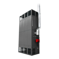
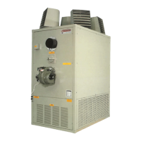
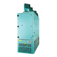
This document provides installation and servicing instructions for the Powrmatic TE range of gas-fired, forced-draught, closed-flue, fanned circulation air heaters. These heaters are primarily designed for commercial or industrial premises and are certified for use with Natural Gas, Group H - G20. They are intended for floor mounting and free-blowing applications only.
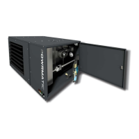
The TE heaters feature a double axial fan assembly positioned upstream of the combustion chamber/heat exchanger. This design circulates the air to be heated efficiently. Standard features include fully automatic monoblock forced-draught gas burners and monoblock gas control assemblies. The heaters are available with either High/Low or modulating burner options, offering flexibility in heating control. Each air heater must be connected to a closed flue system to ensure safe operation.
Installation of these appliances must strictly adhere to the Gas Safety (Installation & Use) Regulations 1994, as well as other relevant requirements from local gas regions, authorities, and fire authorities. It is crucial that all gas appliances are installed, adjusted, and, if necessary, converted by qualified persons to ensure safety and compliance with the law.
The installation process begins with checking local distribution conditions, gas type, pressure, and appliance adjustments for compatibility. The air heater's location is critical; it must allow for a satisfactory flue system, adequate air supply, and sufficient space for servicing and air circulation. The heaters are not designed for corrosive or salty atmospheres, high wind speeds, or outdoor use. If there's a risk of external mechanical damage, the unit must be suitably protected. TE units are designed to operate in a maximum ambient temperature of 25°C.
Regarding gas supply, the local gas undertaking should be consulted early in the planning stage to confirm adequate supply. Existing service pipes and meters must be checked for suitability. Installation pipes must conform to IM/16:1988, ensuring they are of adequate size and tested for soundness. If a gas pressure booster is necessary, controls must include a low-pressure cut-off switch at the booster inlet, and the local gas undertaking must be consulted.
The flue system design is detailed, requiring connection to a closed flue system. The flue's cross-sectional area must not be less than the heater's flue outlet. Materials used for the flue system must be mechanically robust, resistant to corrosion, noncombustible, and durable. To minimize condensation, double-walled flue pipe or insulation is recommended. Provisions for condensation drainage, preferably into a gully, must be made if condensation is unavoidable. The flue pipe(s) must be easily disconnectable for inspection and servicing. The flue should terminate in a freely exposed position, preventing combustion products from entering buildings at harmful concentrations. An approved terminal must be fitted at the flue outlet.
Air supply requirements are also specified, particularly for buildings with low air change rates. Grilles must be provided at low level, with minimum free areas calculated based on total rated heat input. Air vents should have negligible resistance and be sited away from potential blockages, flooding, or adjacent extraction systems carrying flammable vapor. The air distribution system should be designed to avoid impeding air throw and ensure an unobstructed return air path. Care must be taken to keep return-air intakes clear of smells, fumes, and potential pollution sources like dust or shavings. Screens may be necessary to prevent contamination.
Electrical supply to the TE heaters requires a 400V - 3N, 50Hz supply, installed in accordance with I.E.E. Regulations. Wiring should be completed in flexible conduit, and an isolator with at least 3mm contact separation in all poles must be provided adjacent to the heater(s) for complete electrical isolation.
Control thermostat siting is crucial for effective heating. If a remote thermostat is required, it should be placed in a location representative of the heated area, avoiding draughty spots, direct heat sources, or stagnant air. The thermostat should be mounted approximately 1.5m (5ft) from the floor and be of the 'snap action' type, suitable for switching 230V, 5A.
Commissioning and testing procedures ensure the heater's safe and efficient operation. This includes electrical safety checks by a qualified person, gas installation soundness tests, and purging in accordance with IM/16:1988. Fan rotation must be verified, and if incorrect, the direction can be reversed by interchanging two of the 3ph main supply leads. The gas controls assembly undergoes a soundness check, and the burner sequence is verified. Final adjustments involve checking start gas pressure, main burner gas pressure, and CO₂ content of flue gases, adjusting combustion air ratio controls if necessary. A final soundness test of all gas controls assembly joints is performed using leak detection fluid. Control settings for the Eurotrol OSII, including mode and modulating control temperature set point, are also configured.
Handover to the user involves providing instructions for efficient and safe operation, adjusting automatic controls to user requirements, and advising on annual servicing for continued efficiency and safety. If premises are unoccupied, gas and electricity supplies should be turned off, and instructional literature left near the gas meter.
Servicing requires switching off and disconnecting electricity supply and closing the gas service valve before any work is undertaken. Access doors on TE units have electrical interlocks, but these should not be solely relied upon. Full maintenance is recommended at least once per year. After servicing or component replacement, the air heater(s) must be fully commissioned and tested for soundness.
Maintenance tasks include burner maintenance (referencing the burner supplement), heat exchanger cleaning (involving disconnection of gas supply, removal of burner, access plates, baffles, and brushing tubes), and fan assembly inspection (checking blades for damage or deposits, inspecting and replacing drive belts, and lubricating ballrace bearings).
Replacement of faulty components covers burner components, gas controls assembly, main fan motors (requiring release of mounting plate, belt tension adjustment, electrical disconnection, and fitting new motor), main air fan(s) (involving side panel removal, fan shaft locking, and fitting new fan), and air fan pulleys. Belt tension adjustment is specified to a 12mm-15mm deflection.
Fan and limit thermostats (White Rodgers 5F464) are also covered for replacement. This involves removing covers, releasing wiring, accessing the thermostat sensing phial from the heat exchanger, and securing the new unit. Specific settings for Fan ON (50°C), Fan OFF (30°C), and Limit (100°C) are provided.
Fault finding guidance is included, addressing common issues like the main burner not lighting (checking electrical and gas supplies, controls ON/calling for heat), burner lighting but going out before the main fan comes on (checking high limit, fan and limit thermostat settings, faulty fan assembly, fan motor overload), main fan running continuously (checking Summer/Winter switch, faulty fan thermostat), and main fan failing to run (checking fan motor/capacitor, fan thermostat, fan contactor, door interlock).
A short list of parts is referenced, with further details available from Powrmatic Ltd.
| Heat Output | 4.1kW |
|---|---|
| Weight | 13.5kg |
| Thermostat | Yes |
| Remote Control | No |
| Timer | No |
| Ignition Type | Piezo ignition |
| Electrical Supply | Not required |
| Safety Features | Oxygen Depletion Sensor (ODS), flame failure device |