page no. 55 of 68
LX Range Users, Installation & Servicing Instructions Doc Ref M110 issue 1.0 Dec 2020.
2.7 Servicing
2.7.2. Main Burner Assembly Removal
1. Ensure that the gas service valve is turned OFF
and then unscrew the union nut situated immediately
downstream of it.
2. Disconnect the spark and rectification leads from the
control box and remove the electrical plug connections
from the top of the gas control valve assembly.
3. Remove the burner heat shield, 3 screws.
4. Release the inlet connection flange from the gas valve
by removing the four screws.
5. If required remove the manifold by removing the four
screws securing it to the burner assembly.
6. Remove the two screws that secure the top of the
burner assembly to the bulkhead and lift out burner
assembly.
7. Using a stiff brush, not a wire brush, brush the
burners to dislodge accumulated deposits. Inspect the
burners both internally and externally to ensure that
they are clean. Examine the injectors and if damaged or
deteriorated, replace with new ones of the correct size
and marking. If deemed necessary, clean the injectors. Do
not broach out with wire.
8. Reassemble the injectors, manifold and burners in
reverse order to that above.
2.7.3. Ignition and Rectification
Electrodes
Note: The ignition electrode is located at the
bottom of the burner assembly, the
rectification electrode is located at the top of
the burner assembly.
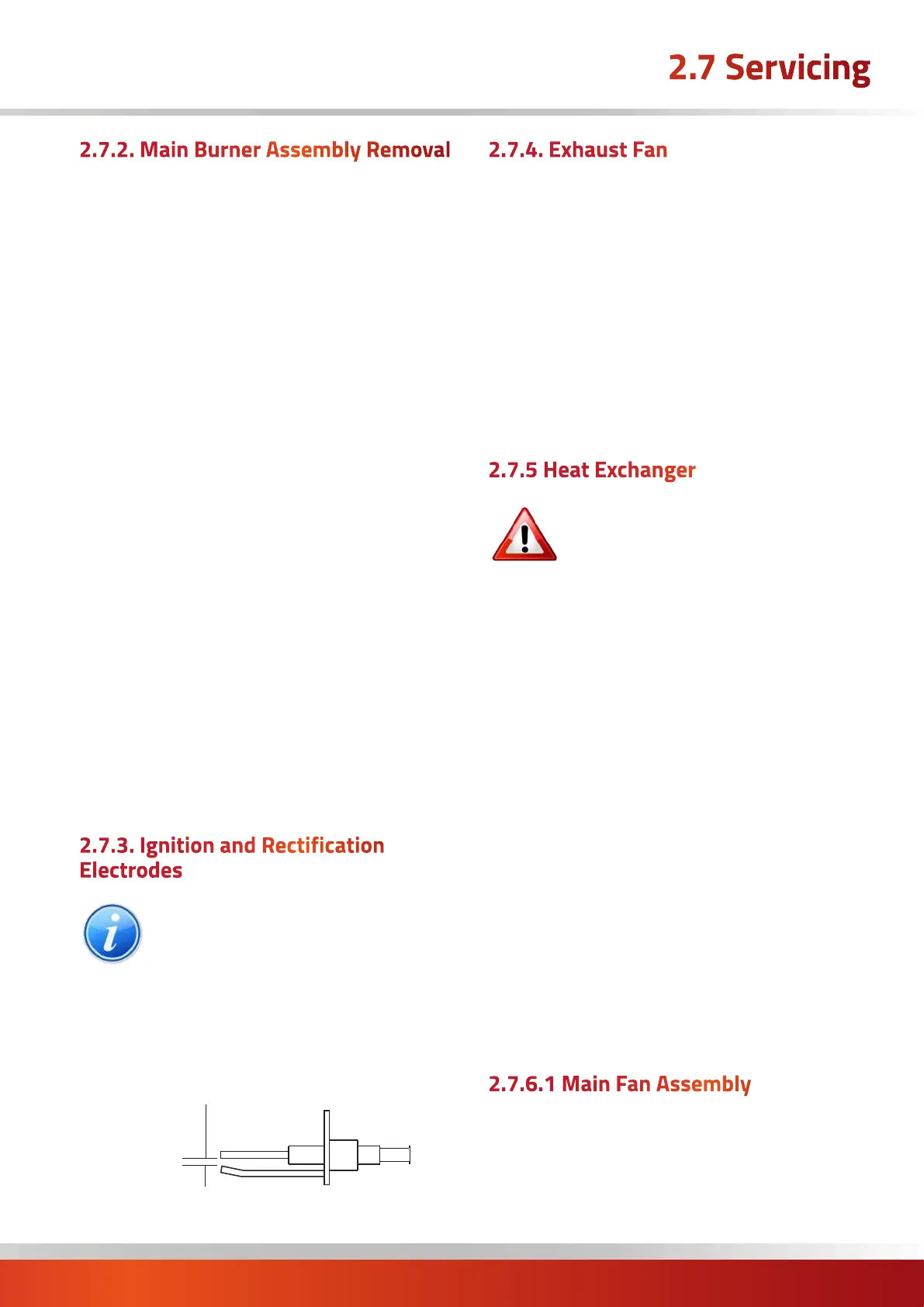
Inspect the electrodes, making sure that they are in a
sound and clean condition. In particular check that the
ignition electrode is clean and undamaged. Check that the
spark gap is 2.5mm and that the rectification probe is 10 -
12mm forward of the burner.
2.5mm
Ignition Electrode Spark Gap
2.7.4. Exhaust Fan
1. Remove the four screws securing the flue outlet socket.
2. Disconnect the fan electrical connections from the main
terminal strip
3. Remove the screws securing the fan mounting box to
the exhaust header plate.
4. Clean impeller by brushing with a stiff brush.
5. Re-assemble using a new sealing gasket to the fan
mounting box. Use silicon sealant around the joints.
2.7.5 Heat Exchanger
It is a requirement of Gas Safe that
the integrity of the combustion circuit
is confirmed during every annual
service.
1. If not already done so, check that the primary sections
of the burner tubes are clean and free from debris (see
section 2.7.2 for burner removal).
2. Once the combustion fan has been removed (see
section 2.7.4 for removal), unscrew and remove the
exhaust collector box to expose the rear sections of the
burner tubes.
3. Carefully remove the swirlers and check for any
deterioration.
4. Check that the integrity of the burner tubes. (See
section 2.7.2 for burner/tube insert removal). Ensure the
tubes are clean and if necessary, brush inside each tube
until all foreign material has been removed.
5. If possible, visually inspect the integrity of the burner
tubes externally. If this is not possible, verification can be
achieved by checking the flue gas composition with a gas
analyser (see section 2.6.6.2).
2.7.6.1 Main Fan Assembly
1. Inspect the fan blades for any damage or excessive
buildup of deposits that could give rise to an imbalance.
Remove the assembly for cleaning as follows.
2. Slacken the cable gland on the heater casing through
which the fan electrical cable passes.
 Loading...