Do you have a question about the Powrmatic CPx Series and is the answer not in the manual?
Perform essential pre-operation checks for safe and correct heater function.
Step-by-step guide for starting gas-fired and oil-fired air heaters.
Instructions for safely turning off the heater for short or long periods.
Overview of the heater's operational sequence and modes (summer/winter).
Explanation of fan/limit control functions and manual reset procedures.
Recommendations for regular servicing to ensure efficiency and safety.
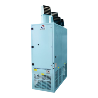
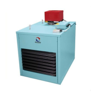
Details on the CPx/NCA style with extended casing for internal applications.
Information on the CPx/EA style, weather-proof for external applications.
Dimensional data for CPx UD/UF upright ducted models (30-300).
Dimensional data for CPx HD/HF horizontal ducted models (30-300).
Dimensional data for CPx-EA upright external cabinet heaters (30-300).
Dimensional data for CPx UD/UF upright ducted models (360-590).
Dimensional data for CPx HD/HF horizontal ducted models (360-590).
Dimensional data for CPx-EA upright external cabinet heaters (360-590).
Dimensional data for CPx-EA horizontal external cabinet heaters (360-590).
Details on side/rear inlet spigots for CPx models.
Information on available filter specifications and options.
Overview of damper options for airflow control.
Visual representations of different air outlet head configurations.
Specifies required clearances around the unit for installation and servicing.
General installation considerations including copper sulphide and combustible materials.
Guidance on mounting the heater and minimum clearances for installation.
Instructions for making safe and proper gas connections.
Guidance on connecting oil supply lines to the heater.
Advice on optimal placement of room thermostats for accurate temperature control.
Safety warnings and requirements for electrical connections.
Diagram illustrating a common wiring setup with a remote controller.
Details on mains supply and integral control wiring terminals.
Information on connecting the main electrical supply (1-phase and 3-phase).
Wiring details for the heater's internal control system.
Table showing standard and LHP fuse ratings for different models.
Wiring details for optional remote control units.
Detailed wiring diagram for 1-phase gas/oil CPx30-90 models.
Detailed wiring diagram for 3-phase gas/oil CPx120-200 models.
Detailed wiring diagram for 3-phase gas/oil CPx250-300 models.
Checks to ensure electrical safety by a qualified person.
Procedures for inspecting, testing, and purging gas installations.
Procedures for inspecting and testing oil installations.
Check installation of delivery ducts, return air paths, and system resistance.
Procedures for safely lighting the heater, including gas and oil models.
Specific commissioning steps for gas-fired heaters.
Specific commissioning steps for oil-fired heaters.
Guidelines for full annual maintenance by a qualified person.
Instructions for removing the main burner assembly for servicing.
Procedures for cleaning the heat exchanger tubes.
Steps for accessing, inspecting, and cleaning the main fan assembly.
Instructions for accessing and cleaning/replacing the oil filter.
Guidance on replacing faulty components, including burner setup.
Procedure for replacing the fan/limit thermostat.
General faults and troubleshooting steps for the heater not turning on or running.
Fault finding for gas models (CPxG030-CPxG250), covering ignition and flame issues.
Continued fault finding for gas models, addressing flame failure and ignition delays.
Part numbers for Riello gas burners with natural gas.
Part numbers for the gas control valve.
Part numbers for burner gaskets for gas and oil applications.
Part numbers for Riello 35s oil burners with nozzle and lead.
Part numbers for 35-second oil nozzles.
Part numbers for 28-second oil nozzles.
Part number for the oil filter.
Part number for the fire valve.
Part number for the L4064 Fan & Limit Thermostat.
Part number for the Limit Interlock PCB.
Part numbers for standard LPH fuses.
Part numbers for LPG conversion kits.
Steps for converting the heater for oil fuel types.
Procedure for changing the burner nozzle during oil conversion.
How to set oil pump pressures for different oil types.
Guide for adjusting high/low pump pressures for oil burners.
Steps for converting the heater between natural gas and propane.
General considerations for gas conversion, including injector and pressure changes.
Process for converting the burner for different gas types.
How to adjust gas valve pressures for natural gas or propane.
Data related to ecodesign requirements and efficiency ratings.
Formulae and data for calculating flue system resistance.
| Airflow | Varies by model |
|---|---|
| Mounting | Suspended |
| Dimensions | Varies by model |
| Weight | Varies by model |
| Voltage | 400 V |
| Application | Industrial, Commercial |
| Heating Element | Stainless Steel |