page no. 12 of 68
CPx Range Users, Installation & Servicing Instructions Doc Ref M201 issue 2.9 Nov 2018.
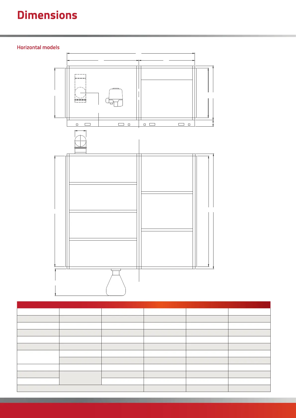
Model 360 440 590
A All mm 1915 2165 2715
B All mm 1260 1330 1330
C All mm 2800 3250 3600
D All mm ø 250 300 300
E All mm 1250 1350 1700
F All mm 1550 1900 1900
G
Gas mm 580 580 840
Oil mm 468 468 680
H All mm 830 865 865
L
Duct Spigot
mm 1815 2065 2615
M mm 1160 1230 1230
Head Plan 3b 4 4
Notes -
• The Heat Exchanger and Fan Section can be split on the ‘Section Split
Line’. Flue tee provided as standard.
• Direction of airflow to be specified at time of order.
Right to Left (R-L when looking at the burner) airflow shown above.
ØD
Section
Split Line
A
L
G
L
M
F
E
C
M B
200
H
Dimensions
CPx HD/HF Upright Free Blowing Upright Ducted (360-590)
Horizontal models

 Loading...