EasyManuals Logo

Powrmatic CPx Series User Manual

Powrmatic CPx Series
68 pages
To Next Page IconTo Next Page
To Previous Page IconTo Previous Page
Page #11 background imageLoading...
Page #11 background image
page no. 11 of 68
CPx Range Users, Installation & Servicing Instructions Doc Ref M201 issue 2.9 Nov 2018.
Notes -
The Heat Exchanger and Fan Section can be split on the ‘Section Split Line’.
Flue tee provided as standard.
Section
Split Line
ØD
G
A
L
J1
J
K
200
B
M
F
C
E
H
Model 360 440 590
A All mm 1915 2165 2715
B All mm 1260 1330 1330
C All mm 2615 3065 3365
D All mm ø 250 300 300
E All mm 865 965 1265
F All mm 1550 1900 1900
G
Gas mm 508 580 840
Oil mm 508 468 680
H All mm 2152 2537 2837
J All mm 558 558 558
J1 All mm 1007 1007 1007
K All mm 431 431 431
L
Duct Spigot
mm 1815 2065 2615
M mm 1160 1230 1230
Head Plan 3b 4 4
Dimensions
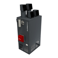
CPx UD/UF Upright Free Blowing Upright Ducted (360-590)
Upright models

Questions and Answers:

Question and Answer IconNeed help?

Do you have a question about the Powrmatic CPx Series and is the answer not in the manual?

Powrmatic CPx Series Specifications

General IconGeneral
BrandPowrmatic
ModelCPx Series
CategoryHeater
LanguageEnglish

Related product manuals