page no. 10 of 68
CPx Range Users, Installation & Servicing Instructions Doc Ref M201 issue 2.9 Nov 2018.
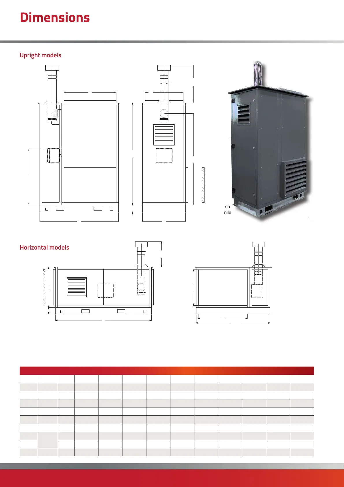
Model 30 45 60 90 120 150 175 200 250 300
A All mm 1184 1184 1379 1379 1692 1692 1891 1891 2280 2280
B All mm 669 669 744 744 904 904 904 904 1104 1104
C All mm 1767 1767 1895 1895 2149 2149 2265 2265 2265 2265
D All mm ø 125 125 150 150 150 175 175 175 200 200
E All mm 150 150 150 150 150 200 200 200 240 240
F All mm 1535 1535 1661 1661 1923 1923 2021 2021 2021 2021
G All mm 864 864 944 944 1122 1122 1122 1122 1122 1122
L
Duct
Spigot
mm 632 632 824 824 1100 1100 1299 1299 1499 1499
M mm 569 569 644 644 804 804 804 804 1004 1004
N All mm 125 125 125
125 150 150 150 150 150 150
Notes -
• Direction of airflow to be specified at time of order. Left to Right (L-R when looking at the burner) airflow shown above.
• Inlet and Outlet duct spigots have the same dimensions (Horizontal units only)
• Primary flue length, cowl and flashing provided as standard.
N
B
C
Optional
Fresh Air
Intake
Grille
A
L
M
1 mtr
A
L
ØD
M
C
N
B
F
Optional Fresh
Air Intake Grille
1 mtr
E
G
Dimensions
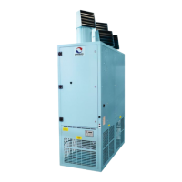
CPx-EA External Cabinet Heaters (30-300)
Upright models
Horizontal models

 Loading...