EasyManua.ls Logo

Powtran PI500 015G3 User Manual

Powtran PI500 015G3
112 pages
To Next Page IconTo Next Page
Page #1 background imageLoading...
Page #1 background image
Foreword
Thank you for choosing Powtran PI500 Series Frequency Inverter. This
product made by Powtran is based on years of experience in professional
production and sale, and designed for variety of industrial machinery, fan and
water pump drive unit and IF heavy-duty grinding unit.
This manual provides user the relevant precautions on installation,
operational parameter setting, abnormal diagnosis, routine maintenance and
safe use. In order to ensure correct installation and operation of the frequency
converter, please carefully read this manual before installing it.
For any problem when using this product, please contact your local dealer
authorized by this company or directly contact this company, our professionals
are happy to serve you.
The end-users should hold this manual, and keep it well for future
maintenance & care, and other application occasions. For any problem within
the warranty period, please fill out the warranty card and fax it to the our
authorized dealer.
The contents of this manual are subject to change without prior notice. To
obtain the latest information, please visit our website.
For more product information, please visit: http:// www.powtran.com.
Powtran
March , 2018

Table of Contents

Other manuals for Powtran PI500 015G3

Question and Answer IconNeed help?

Do you have a question about the Powtran PI500 015G3 and is the answer not in the manual?

Powtran PI500 015G3 Specifications

General IconGeneral
CategoryDC Drives
BrandPowtran
Rated Output Current30A
Cooling MethodForced air cooling
Enclosure RatingIP20
Control MethodVector control
Overload Capacity150% rated current for 60 seconds
Protection FeaturesOvercurrent, Overvoltage, Undervoltage, Short Circuit, Phase Loss
Communication InterfaceRS485
ModelPI500-015G3
Rated Input Voltage3-phase 380V ±15% (50/60Hz)

Summary

Chapter 1 Inspection and Safety Precautions

Safety Precautions

Essential safety measures during installation, wiring, operation, and maintenance.

Precautions

Specific precautions for motor insulation, thermal protection, frequency, vibration, and adaptive motors.

Chapter 2 Standard Specifications

Technical Specifications

Detailed technical specifications including model, power, current, and adaptive motor capacity.

Chapter 3 Keyboard

Chapter 4 Installation and Commissioning

Installation Direction and Space

Guidelines for inverter installation orientation and required surrounding space.

Wiring Diagram

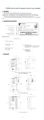
Diagrams illustrating the main and control circuit wiring connections for the inverter.

Main Circuit Terminal

Arrangement and function description of the main circuit terminals for various power ratings.

Control Circuit Terminals

Description of control circuit terminals, including power supply and signal connections.

Wiring Precautions

Critical precautions to ensure safe and correct wiring of the inverter.

Commissioning

Step-by-step guide for commissioning the inverter after installation.

Chapter 5 Function Parameter

F0 Group - Basic Function Group

Basic function parameters including motor control, frequency setting, and acceleration/deceleration.

F1 Group - Input Terminals Group

Parameters for configuring digital and analog input terminals.

F2 Group - Output Terminals Group

Parameters for configuring digital, relay, and analog output terminals.

F3 Group - Start and Stop Control Group

Parameters related to start-up modes, speed tracking, and stop modes.

F4 Group - V/F Control Parameters

Parameters for configuring V/F curve settings, torque boost, and voltage control.

F5 Group - Vector Control Parameters

Parameters for vector control, including speed loop, torque limit, and proportional/integral gains.

F8 Group - Fault and Protection

Parameters for configuring fault detection, protection actions, and alarms.

F9 Group - Communication Parameter

Parameters for setting communication protocols, baud rate, and data formats.

FA Group - Torque Control Parameters

Parameters for torque control mode, setting source, and acceleration/deceleration times.

E2 Group - PID Function

Parameters for configuring PID control, including source, feedback, and action direction.

b0 Group -Motor Parameters

Parameters related to motor configuration, including type, rated values, and resistance.

Chapter 6 Troubleshooting

Fault Alarm and Countermeasures

Table of fault codes, possible causes, and recommended solutions for inverter issues.

Chapter 8 Maintenance and Repair

Inspection and Maintenance

Routine inspection points and methods for maintaining inverter performance.

Appendix I RS485 Communication Protocol

Related product manuals