EasyManua.ls Logo

Powtran PI500 5R5G1 User Manual

Powtran PI500 5R5G1
112 pages
To Next Page IconTo Next Page
Page #1 background imageLoading...
Page #1 background image
Foreword
Thank you for choosing Powtran PI500 Series Frequency Inverter. This
product made by Powtran is based on years of experience in professional
production and sale, and designed for variety of industrial machinery, fan and
water pump drive unit and IF heavy-duty grinding unit.
This manual provides user the relevant precautions on installation,
operational parameter setting, abnormal diagnosis, routine maintenance and
safe use. In order to ensure correct installation and operation of the frequency
converter, please carefully read this manual before installing it.
For any problem when using this product, please contact your local dealer
authorized by this company or directly contact this company, our professionals
are happy to serve you.
The end-users should hold this manual, and keep it well for future
maintenance & care, and other application occasions. For any problem within
the warranty period, please fill out the warranty card and fax it to the our
authorized dealer.
The contents of this manual are subject to change without prior notice. To
obtain the latest information, please visit our website.
For more product information, please visit: http:// www.powtran.com.
Powtran
March , 2018

Table of Contents

Other manuals for Powtran PI500 5R5G1

Question and Answer IconNeed help?

Do you have a question about the Powtran PI500 5R5G1 and is the answer not in the manual?

Powtran PI500 5R5G1 Specifications

General IconGeneral
Power5.5 kW
Voltage380V
Current11 A
Output Current11 A
Frequency Range0-400 Hz
Communication InterfaceRS485
Cooling MethodForced Air Cooling
Storage Temperature-20°C to +60°C
Altitude≤1000 m
Input Voltage3-phase 380V ±15%
Control MethodV/F control
Protection FeaturesOvercurrent, Overvoltage, Undervoltage, Overheat
Operating Temperature-10°C to +40°C
Humidity≤95% RH (non-condensing)

Summary

Chapter 1 Inspection and Safety Precautions

1-1. Inspection After Unpacking

Procedures for checking the unit and its components after receiving it.

1-2. Safety Precautions

Guidelines and warnings to prevent injury and equipment damage during operation.

Chapter 2 Standard Specifications

Chapter 3 Keyboard

3-3. Description of Operation Panel Keys

Details the function of each key on the control panel for navigation and operation.

Chapter 4 Installation and Commissioning

4-1. Installation Direction and Space

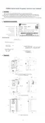
Specifies requirements for mounting orientation and clearance for proper ventilation.

4-2. Wiring Diagram

Illustrates the main circuit and control circuit connections for the inverter.

4-3. Main Circuit Terminal

Details the arrangement and function of terminals for power input and motor output.

4-4. Control Circuit Terminals

Explains the arrangement and function of terminals for external control signals and sensors.

4-5. Wiring Precautions

Crucial safety warnings and guidelines for performing wiring operations correctly.

4-7. Commissioning

Outlines the steps for setting up and verifying the inverter's operation after installation.

Chapter 5 Function Parameter

5-1-2. F0 Group - Basic Function Group

Covers fundamental settings including motor control mode, frequency sources, and acceleration/deceleration.

5-1-3. F1 Group - Input Terminals Group

Details the configuration of digital and analog input terminals for control and feedback.

5-1-4. F2 Group - Output Terminals Group

Explains the settings for digital and analog output terminals to signal inverter status.

5-1-5. F3 Group - Start and Stop Control Group

Defines parameters for controlling the inverter's start-up, stop modes, and speed tracking.

5-1-10. F8 Group - Fault and Protection

Configuration of various protection mechanisms and fault handling actions.

5-1-19. b0 Group - Motor Parameters

Essential parameters for motor configuration, including type, voltage, current, and resistance.

Chapter 6 Troubleshooting

6-1. Fault Alarm and Countermeasures

Lists common fault codes, their causes, and recommended solutions for troubleshooting.

Chapter 8 Maintenance and Repair

8-1. Inspection and Maintenance

Routine inspection checklist and criteria for ensuring the inverter's reliable operation.

Appendix I RS485 Communication Protocol

I-1. Communication Protocol

Defines the communication content, bus structure, and topological setup for RS485.

Appendix II How to Use Universal Encoder Expansion Card

Appendix IV Instruction of Profitbus –DP Communication Card

Appendix V Product Application Case

Related product manuals