2
BASIC OPERATIONS
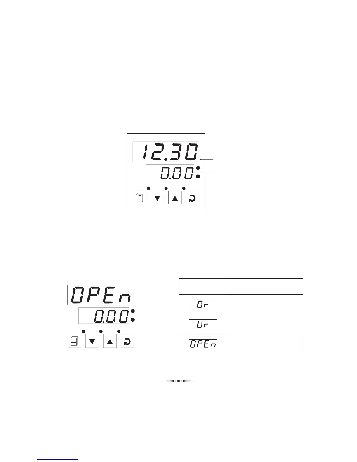
MAIN DISPLAY MODE
After the power-up display sequence, the upper readout starts showing the measured PV (Process Value) and the lower
readout displays the SP (Setpoint) in 0.01°C Resolution.
This is called the MAIN display mode and this is the one that shall be used most often. The MAIN display mode is depicted in
Figure 2.1.
Figure 2.1
PV ERROR INDICATIONS
In case the PV falls below the Minimum Range or rises above the Maximum Range specified for the RTD Pt100 input type or in
case the RTD Pt100 sensor is open / broken; the upper readout flashes the error messages listed in Table 2.1 below. The
Figure 2.2 illustrates an open sensor condition.
Message PV Error Type
Over-range
(PV above Max. Range)
Under-range
(PV below Min. Range)
Open
(Sensor open / broken)
Table 2.1
User Manual
Zenex-ultra
Section 2
PV
SP
PPI
zenex-ultra
OP1 OP2
OP3
S
T
Figure 2.2
PPI
zenex-ultra
OP1 OP2
OP3
S
T