5
The installation parameters are contained in PAGE-10 and are required to be set only at the time of a new installation.
The installation parameters are listed below in Table 4.1, followed by the definitions for each parameter.
INSTALLATION PARAMETERS
Table 4.1
Settings
(Default Value)
Parameter Description
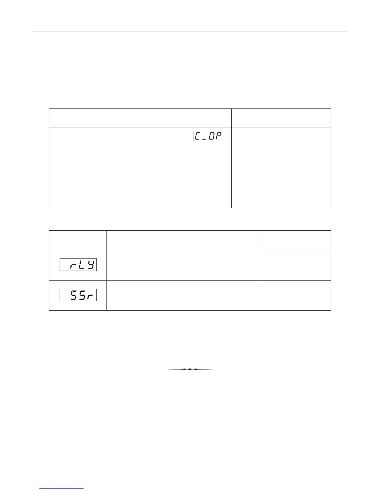
OUTPUT TYPE
The controller is supplied with built-in Relay and DC voltage
pulses (for driving external SSR) as control output signals. The
required output type can be selected by appropriate jumper
settings as described in section 9: Hardware Assembly And
Configurations. The jumper-selected output type must also be set
as a value for this parameter for correct operation. The controller
automatically sets the cycle time for the time-proportioning PID
output in accordance with the selected output type. The Table 4.3
below lists the options available for setting this parameter value.
Refer Table 4.2
(Default : SSR)
Table 4.2
Option
What it means
Cycle Time
Electromechanical Relay contacts
(Common & Normally Open)
DC voltage pulses for driving
external Solid State Relay (SSR)
20 Seconds
1 Second
Note:
In the zenex-ultra, the Temperature Range is restricted to -19.99 to +102.9°C. This Temperature Range is fixed and not available as settable
parameter. The 0.01°C Resolution is available upto 99.99°C. After this, the resolution automatically changes to 0.1°C.
User Manual
Zenex-ultra
Section 4
 Loading...