6
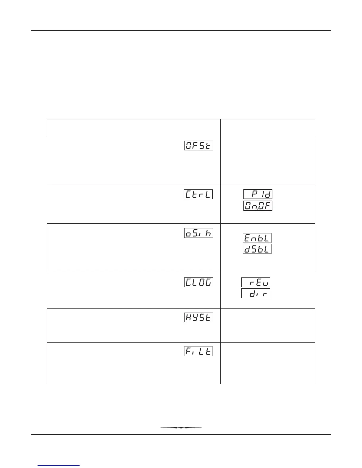
The Configuration parameters are contained in PAGE-11 and are factory set to the appropriate default values. However, for
specific installations the user may need to alter the values. Altering the configuration parameter values affect either the
measured PV and/or the control algorithm implemented by the controller. The parameters are listed in Table 5.1 below,
followed by their definitions.
CONFIGURATION PARAMETERS
Table 5.1
Settings
(Default Value)
Parameter Description
-19.99 to +25.00
(Default : 0.00)
Enable
Disable
(Default : Enable)
Reverse
Direct
(Default : Reverse)
User Manual
Zenex-ultra
CONTROL LOGIC
Select Reverse (heat logic) or Direct (cool logic).
OVERSHOOT INHIBIT
(Available for PID control only)
Enabling this feature controls the PV rise or fall upon process
start-up in order to reach the control setpoint with as minimum
overshoot as possible.
CALIBRATION OFFSET
This value is algebraically added to the measured PV to derive the
final PV that is displayed and compared for alarm / control.
Final PV = Measured PV + Offset
CONTROL MODE
Select appropriate Control Algorithm suited for process
requirement.
(Default : PID)
On-Off
PID
0.10 to 25.00
(Default : 0.20)
1.0 to 25.0 Seconds
in steps of 0.5 Seconds
(Default :1.5)
HYSTERESIS
(Available for On-Off or Pulsed On-Off Control only)
Sets differential (dead) band between On-Off switching for OP1.
DIGITAL FILTER FOR PV
Sets the time constant, in seconds, for the low-pass digital filter
applied to the measured PV. The filter helps smoothing /
averaging the signal input and removing the undesired noise.
Note:
The Calibration Offset and Hysterisis parameter values are settable same as that for the PV resolution. Hence, they are also available in
0.01°C resolution. Their settings and default values are modified as per the 0.01°C resolution as shown in the above Table 5.1.
Section 5


 To Next Page