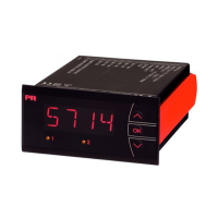
5714V104-UK 5
Environment
Avoid direct sun light, dust, high temperatures, mechanical vibrations and shock, and rain and heavy moisture. If necessary,
heating in excess of the stated limits for ambient temperatures should be avoided by way of ventilation.
All devices fall under Installation Category II, Pollution Degree 2, and Insulation Class II.
Mounting
Only technicians, who are familiar with the technical terms, warnings, and instructions in the manual and who are able to
follow these, should connect the device. Should there be any doubt as to the correct handling of the device, please contact
your local distributor or, alternatively,
PR electronics A/S
www.prelectronics.com
Mounting and connection of the device should comply with national legislation for mounting of electric materials, i.e. wire
cross section, protective fuse, and location. Descriptions of input / output and supply connections are shown in the block
diagram and side label.
The following apply to fixed hazardous voltages-connected devices:
The max. size of the protective fuse is 10 A and, together with a power switch, it should be easily accessible and close to
the device. The power switch should be marked with a label telling it will switch off the voltage to the device.
Year of manufacture can be taken from the first two digits in the serial number.
UL installation requirements
For use on a flat surface of a type 1 enclosure
Use 60/75°C copper conducters only
Enclosure rating (face only) acc. to UL50E. . . . . . . . . . . . . . . . . . . . . Type 4X
Max. ambient temperature . . . . . . . . . . . . . . . . . . . . . . . . . . . . . . 60°C
Max. wire size, pins 41...46. . . . . . . . . . . . . . . . . . . . . . . . . . . . . . AWG 30-16
Max. wire size, others . . . . . . . . . . . . . . . . . . . . . . . . . . . . . . . . . AWG 30-12
UL file number . . . . . . . . . . . . . . . . . . . . . . . . . . . . . . . . . . . . . E248256
Relay outputs:
Max. voltage . . . . . . . . . . . . . . . . . . . . . . . . . . . . . . . . . . . . . . 250 VRMS
Max. current. . . . . . . . . . . . . . . . . . . . . . . . . . . . . . . . . . . . . . . 2 A / AC
Max. AC power . . . . . . . . . . . . . . . . . . . . . . . . . . . . . . . . . . . . . 500 VA
Max. current at 24 VDC . . . . . . . . . . . . . . . . . . . . . . . . . . . . . . . . 1 A
Calibration and adjustment
During calibration and adjustment, the measuring and connection of external voltages must be carried out according to the
specifications of this manual. The technician must use tools and instruments that are safe to use.
Normal operation
Operators are only allowed to adjust and operate devices that are safely fixed in panels, etc., thus avoiding the danger of
personal injury and damage. This means there is no electrical shock hazard, and the device is easily accessible.
Cleaning
When disconnected, the device may be cleaned with a cloth moistened with distilled water.
Liability
To the extent the instructions in this manual are not strictly observed, the custom er cannot advance a demand against PR
electronics A/S that would otherwise exist according to the concluded sales agreement.

 Loading...