EasyManua.ls Logo

PR electronics PReview 5515 - User Manual

PR electronics PReview 5515
35 pages
Go to English
Print Icon
To Next Page IconTo Next Page
Loading...
Programmable displays with a wide se-
lection of inputs and outputs for display of temperature,
volume and weight, etc. Feature linearisation, scaling,
and difference measurement functions for programming
via PReset software.
Interfaces for analogue and digital
signals as well as HART
®
signals between sensors / I/P
converters / frequency signals and control systems in Ex
zone 0, 1 & 2 and for some modules in zone 20, 21 & 22.
Galvanic isolators for analogue and digital
signals as well as HART
®
signals. A wide product range
with both loop-powered and universal isolators featuring
linearisation, inversion, and scaling of output signals.
PC or front programmable modules with
universal options for input, output and supply. This range
offers a number of advanced features such as process
calibration, linearisation and auto-diagnosis.
A wide selection of transmitters for DIN
form B mounting and DIN rail modules with analogue
and digital bus communication ranging from application-
specifi c to universal transmitters.
Displays
Temperature
Isolation
Ex barriers
Universal
DK
UK
FR
DE
Side 1
Page 17
Page 33
Seite 49
SIGNALS THE BEST
5515
Programmable
LCD / LED Indicator
No. 5515V102-IN (0651)
From ser. no. 970015001
Question and Answer IconNeed help?

Do you have a question about the PR electronics PReview 5515 and is the answer not in the manual?

PR electronics PReview 5515 Specifications

General IconGeneral
InputRTD, thermocouple, resistance, potentiometer
Output0/4-20 mA, relay
Operating temperature-20°C to +60°C
CommunicationModbus RTU
Power Supply10.5 - 55 V DC

Summary

Product Displays

Product Ex Barriers

Product Isolation

Product Temperature Transmitters

Product Universal Modules

Safety Warnings

General Safety Warning

Warning for general use, connection to hazardous voltages, and adherence to safety instructions.

Hazardous Voltage Safety

Warning regarding connecting hazardous voltages to the module before fixing it.

Installation Safety

Warning about maintaining safety distances and connecting voltages to relay contacts.

Safety Instructions

Definitions

Defines hazardous voltages, technicians, and operators for safe operation.

Receipt and Unpacking

Instructions for unpacking and verifying the module upon receipt.

Environment

Guidelines for avoiding adverse environmental conditions during operation.

Mounting Instructions

Guidance for technicians on proper module mounting and connection.

Calibration and Adjustment

Procedures for calibrating and adjusting the module safely.

Normal Operation

Guidelines for operators during normal use of the module.

Cleaning Instructions

Method for cleaning the module when disconnected.

Liability Clause

Statement regarding liability for non-compliance with manual instructions.

Declaration of Conformity

DIP Switch and Connection Setup

DIP Switch Configuration

Instructions on adjusting dipswitch configuration and displaying connections.

Loop Link Connection

Guidance on connecting to the programming unit Loop Link.

Product Overview and Inputs

General Description

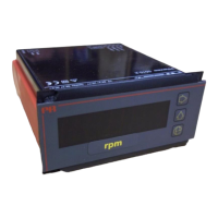
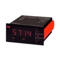
Overview of the 5515 indicator for digital readout of signals.

Input Types for 5515 A1;B1

Details on thermocouple and mV inputs for specific models.

Input Types for 5515 A2;B2

Details on current and voltage inputs for specific models.

Display Features

Description of the 4-digit LCD/LED display and its functions.

Installation and Communication

Information on installation, Loop Link, and communication protocols.

Electrical Specifications

Specifications Range

Specifies the operating temperature range for the device.

Common Specifications

Details supply voltage, consumption, isolation, and communication specs.

TC Input Specifications

Technical specifications for Thermocouple (TC) inputs.

mV Input Specifications

Technical specifications for millivolt (mV) inputs.

Input and Approval Specifications

RTD; lin. R Input Specifications

Technical specifications for RTD and linear resistance inputs.

Voltage and Current Input Specs

Technical specifications for voltage and current inputs.

Display Specifications

Details on display digit height, update rate, and error indication.

Approvals and Standards

Information on GOST R approval and observed authority requirements.

Ordering, Diagrams, and Routing

Product Ordering Information

Table detailing product types, displays, inputs, and supply options.

Block Diagrams

Schematic diagrams illustrating the internal workings of the device.

Routing Diagram

Diagram showing the operational flow and menu structure.

Appendix and Special Versions

5515 A-,PEAK Special Version

Description of the 5515A PEAK version with continuous min/max storage.

5515 A-,PEAK Routing Diagram

Routing diagram specific to the 5515A PEAK version.

Company Information and Subsidiaries

Company Product Overview (Multilingual)

Overview of PR electronics' products and technology in multiple languages.

Subsidiaries Contact Information

List of international subsidiaries with contact details.

Head Office Contact

Contact information for the Denmark head office.

Certifications and Guarantees

Information on quality system certifications and product guarantees.

Related product manuals