Do you have a question about the PR electronics 5714 Series and is the answer not in the manual?
Details I.S. interfaces with SIL 2 Full Assessment, offering multifunctional inputs and outputs.
Covers general safety advice and specific warnings for hazardous voltages.
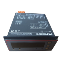
Specifies operating conditions and details mounting procedures, wire requirements, and fuses.
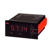
Lists main features like LED indicator, input types, relays, analog output, and universal voltage.
Illustrates connections for current, voltage, potentiometer, RTD, and TC inputs.
Shows connections for analog output (mA) and relay outputs.
Lists basic accuracy and temperature coefficients for mA, Volt, Pt100, resistance, and TC inputs.
Details minimum and maximum values for various TC input types like B, E, J, K, L, N, R, S, T, U, W3, W5, LR.
Lists input types like Pt100, Ni50, Cu10, Lin. R, and Potentiometer with their ranges.
Details relay function, hysteresis, on/off delay, and maximum load ratings.
Explains sensor error detection settings for different 5714 variants.
Diagrams showing connections for RTD, TC, current, voltage, and potentiometer inputs.
Diagrams showing connections for current output and relay outputs.
Illustrates the internal structure including CPU, AD, EEPROM, and I/O connections.
Shows how input signals are processed and output signals are generated.
Details menu options for setting relay behavior, hysteresis, and error conditions.
Lists hardware error codes (HW.ER, EE.ER, RA.ER, CJ.ER) and their meanings.
Details parameters for relay setup, hysteresis, error detection (O.ERR), and response time.
Details how to quickly change set points and test relay operation.
| Brand | PR electronics |
|---|---|
| Model | 5714 Series |
| Category | Measuring Instruments |
| Language | English |