EasyManua.ls Logo

PR electronics 5511 User Manual

PR electronics 5511
73 pages
Go to English
To Next Page IconTo Next Page
Page #1 background imageLoading...
Page #1 background image
Programmable displays with a wide selection of inputs
and outputs for display of temperature, volume and
weight, etc. Feature linearisation, scaling, and difference
measurement functions for programming via PReset soft-
ware.
Interfaces for analogue and digital signals as well as
HART
®
signals between sensors / I/P converters / fre-
quency signals and control systems in Ex zone 0, 1 & 2
and for some modules in zone 20, 21 & 22.
Galvanic isolators for analogue and digital signals as well
as HART
®
signals. A wide product range with both loop-
powered and universal isolators featuring linearisation,
inversion, and scaling of output signals.
PC or front programmable modules with universal options
for input, output and supply. This range offers a number of
advanced features such as process calibration, linearisa-
tion and auto-diagnosis.
A wide selection of transmitters for DIN form B mounting
and DIN rail modules with analogue and digital bus com-
munication ranging from application-specifi c to universal
transmitters.
DK
UK
FR
DE
Side 1
Page 37
Page 73
Seite 107
SIGNALS THE BEST
5511
Universal Indicator
No. 5511V103-IN (0620)
From ser. no. 970284001

Table of Contents

Question and Answer IconNeed help?

Do you have a question about the PR electronics 5511 and is the answer not in the manual?

PR electronics 5511 Specifications

General IconGeneral
BrandPR electronics
Model5511
CategoryMeasuring Instruments
LanguageEnglish

Summary

PR Electronics Product Range

Displays, Interfaces, and Isolators

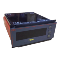
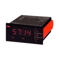
Programmable displays, signal interfaces, and galvanic isolators.

5511WEIG Programming Routing Diagram

Basic Operation and Relay Configuration

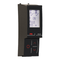
Power-on, navigation, and configuration of relays (set, reset, delay).

Safety Warnings and Symbol Identification

General Warning

General warning about hazardous voltages and proper application.

Hazardous Voltage Warning

Warning regarding connecting hazardous voltages until module is fixed.

Installation Warning

Warning for installation safety, relay contact connections.

Symbol Identification

Explanation of symbols like exclamation mark, CE mark, double insulation.

Detailed Safety Instructions

Mounting and Connection

Guidelines for safe mounting and connection by qualified technicians.

Universal Indicator 5511 Features

Input Type Specifications

Details on Thermocouple, RTD, Resistance, Current, and Voltage inputs.

Display and Electrical Specifications

Common Specifications

Supply voltage, frequency, consumption, isolation, interface, and signal dynamics.

TC Input Specifications

Temperature ranges, span, and accuracy for Thermocouple inputs.

Input and Output Electrical Specifications

Hardware Programming and Mechanical Specifications

Mechanical Specifications and Layout

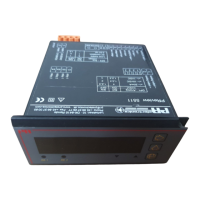
Dimensions, panel cutout, front layout, and terminal placement.

Wiring Diagrams for RTD and Resistance Input

2-Wire and 3-Wire RTD/Resistance Input

Wiring diagrams for 2-wire and 3-wire RTD/resistance sensors.

4-Wire and Differential RTD/Resistance Input

Wiring diagrams for 4-wire and differential RTD/resistance sensors.

Wiring Diagrams for Thermocouple Input

TC Input with Internal/External CJC

Wiring for TC input with internal or external cold junction compensation.

Wiring Diagrams for DC Voltage Input

Wiring Diagrams for DC Current and Bridge Input

Power, Analogue, and Relay Outputs Wiring

Wiring for power supply, analogue output, and relay outputs.

Operating the Function Keys

Advanced Functions and Calibration

Related product manuals