46 47
Relay output (relay 1 and 2) is selected as a make or break function. The relays
can be used as trip amplifier or / and sensor / cable error alarm for a TC, an RTD,
a resistance input and current input.
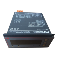
DISPLAY:
4½ digit LCD or LED display with 14 mm digit height. Max. display readout
±19999 with selectable decimal point, relay ON/OFF indication and tendency
readout for the input signal.
From the function keys in the front it is possible to change the limit values and
delay for relays, display updating time, display scaling, decimal point, resolution
on the last digit, analogue output scaling, and calibration of cable resistance.
Moreover, the LCD display has bargraph indication and the light intensity of the
LED display can be changed.
ELECTRICAL SPECIFICATIONS - TYPE 5511:
Specifications range:
-20°C to +60°C
Common specifications:
Supply voltage ............................................ 21.6...253 VAC
19.2...300 VDC
Frequency .................................................... 50...60 Hz
Internal consumption, LED / LCD ............... 3 W / 2 W
Max. consumption, LED / LCD ................... 4 W / 3 W
Fuse ............................................................. 400 mA T / 250 VAC
Isolation, test / operation ............................ 3.75 kVAC / 250 VAC
Communications interface .......................... Opto Link 5901
Signal / noise ratio, analogue output .......... Min. 60 dB
Signal dynamics, input ................................ 23 bit
Signal dynamics, output ............................. 16 bit
Response time (programmable)
min. ...................................................... Updating time x 2.5
max. ..................................................... 250 s
Updating time .............................................. 250 ms
Calibration temperature .............................. 20...28°C
Temperature coefficient ............................... < ±0.01% of span / °C
Linearity error .............................................. < 0.1% of span
Effect of supply voltage change ................. < 0.001% of span / %V
Auxiliary voltages:
Loop supply ................................................ 20 VDC / 20 mA
Reference voltage ....................................... 2.5 VDC ±0.5% / 15 mA
Excitation supply ......................................... 8 VDC ±0.5% / 25 mA
EMC immunity influence ............................. < ±0.5%
Max. wire size .............................................. 1 x 2.5 mm
2
stranded wire
Screw terminal torsion ................................ 0.5 Nm
Relative air humidity .................................... < 95% RH (non-cond.)
Dimensions (HxWxD) ................................... 48 x 96 x 120 mm
Installation dimensions (HxW) ..................... 44.5 x 91.5 mm
Tightness (mounted in panel front) ............. IP65
Weight ......................................................... 300 g
Electrical specifications - input:
TC input:
Max. offset .................................................. 75% of selected max. value
Sensor error current .................................... Nom. 5 µA
Updating time (int./ext.CJC/diff.) ................ 250 ms
Basic accuracy:
Type E,J,K,L,N,T,U ....................................... < ±0.5°C
Type B,R,S,W3,W5 ...................................... < ±2°C
Cold junction compensation (CJC) ............. < ±0.5°C
Min. Max. Min.
Type temperature temperature span Standard
B +400°C +1820°C 200°C IEC584
E -200°C +1000°C 50°C IEC584
J -210°C +1200°C 50°C IEC584
K -180°C +1372°C 50°C IEC584
L -200°C +900°C 50°C DIN43710
N -180°C +1300°C 100°C IEC584
R -50°C +1760°C 200°C IEC584
S -50°C +1760°C 200°C IEC584
T -200°C +400°C 50°C IEC584
U -200°C +600°C 50°C DIN43710
W3 0°C +2300°C 200°C ASTM E988-90
W5 0°C +2300°C 200°C ASTM E988-90