44 45
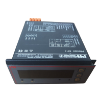
UNIVERSAL INDICATOR 5511
LCD or LED display, 48 x 96 mm
Programmable via PC
Galvanic isolation, 3.75 kVAC
Trip amplifiers and analogue output
Universal voltage supply
Protection IP65 from front
GENERAL:
The PReview indicator is configured to the present application by means of a
PC using the installation program PReset 5000 with associated optical link for
communication between indicator and a DOS-based PC.
Opto Link 5901 is a configuration kit containing an optical link, a PC cable and
the program PReset 5000 for set up of the 5111 and the 5511.
The indicator is configured from factory according to specifications or the user
can do the configuration himself by means of the PReset 5000 program.
The indicator input can be programmed as a TC, an RTD and a resistance input
and a unipolar or bipolar mV, mA, and voltage input.
The output (option) can be a unipolar / bipolar current or voltage signal.
Furthermore, it is possible to insert special linearisation algorithms e.g. in
connection with measurement of non-linear signals.
With the relay option it is possible to insert limit values and achieve digital on/off
signals in connection with temperature sensors or current / voltage signals.
INPUT TYPES:
Thermocouple input: (TC) with 15 bit bipolar resolution for standard
thermocouples in the temperature ranges acc. to the IEC 584, the DIN 43710
or ASTM E988-90 standards. The CJC-function is implemented with a Pt100
sensor in the terminal (option - type no. 5911), external Pt100 sensor or fixed
CJC (thermostat box).
Sensor error detection available.
RTD input in ranges with 16 bit resolution for Pt100, Ni100 in temperature ranges
acc. to the IEC 751 / DIN 43760 standards. Set-up of main type is possible in
multipla (e.g. Pt50 and Ni1000).
Automatic cable compensation by 3- or 4-wire sensor connection.
By 2-wire sensor connection it is possible to compensate cable resistance with
the function keys directly from the front cover.
Sensor error detection available.
Resistance input in ranges with 16 bit resolution for resistance measurement.
Max. range 5 kΩ. Cable compensation by 3- or 4-wire connection.
0% and 100% process calibration is possible with the function keys directly from
the front cover.
Cable breakage detection available.
Current input in ranges with a 15 bit bipolar resolution for DC current signals.
0% and 100% process calibration is possible with the function keys directly from
the front cover.
Cable breakage detection available on 4...20 mA signals.
Voltage input in ranges with a 15 bit bipolar resolution for DC voltage signals, 3-
wire potentiometer, load cells, pressure transducers etc. 0% and 100% process
calibration is possible with the function keys directly from the front cover.
AUXILIARY SUPPLIES:
(Selected by internal DIP-switches).
Loop supply 20 VDC/20 mA for supply of 2-wire transmitter.
Reference voltage 2.5 VDC, 15 mA as reference for 3-wire potentiometers e.g.
as position indicator from analogue valves etc.
Excitation voltage 8 VDC, 25 mA for supply of load cells, pressure transducers
etc.
OUTPUTS: (OPTION)
(Selected by internal DIP-switches).
Current output with 13 bit bipolar resolution programmable in the range ±20 mA
by a maximum offset of 75% of max. output value.
Voltage output with 13 bit bipolar resolution in the ranges ±1 VDC and ±10 VDC.
Max. load 20 mA.