42 43
HOW TO ADJUST DIP-SWITCHES
AND DISPLAY OF CONNECTIONS ON
SYSTEM 5500
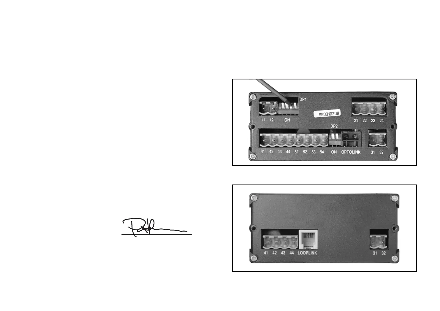
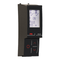
Picture 1 shows how to adjust the DIP-switch configuration. Also, the connection
to Opto Link on the 5511 module is shown.
Picture 2 shows the connector to the programming unit Loop Link.
Picture 1: Adjustment of DIP-switches and display of connections.
Picture 2: Connector to the programming unit Loop Link.
DECLARATION OF CONFORMITY
As manufacturer
PR electronics A/S
Lerbakken 10
DK-8410 Rønde
hereby declares that the following product:
Type: 5511
Name: Universal indicator
is in conformity with the following directives and standards:
EMC directive 2004/108/EC and later amendments
EN 61326
For specification of the acceptable EMC performance level, refer to the
electrical specifications for the module.
The Low Voltage directive 73/23/EEC and later amendments
EN 61010-1
The CE mark for compliance with the Low Voltage directive was affixed in the
year: 1997
Rønde, 19 May 2006 Peter Rasmussen
Manufacturer’s signature