0000
PASSW.
Txt 1
0000
9999
NO
ADV.SET
Txt 2
NO
YES
1 21 2
*1.1
OFF
ON
YES
ADV.SET
Txt 2
NO
YES
1 2
YES
CA.BR
Txt 4
NO
YES
1 2
YES
CA.SH
Txt 3
NO
YES
1 2
33
3
3
3
*1.0
1
DIR
CH2.FUN
Txt 7
DIR
INV
1 2
DIR
CH1.FUN
Txt 7
DIR
INV
1 2
3
3
3
OFF
CA.BR
Txt 18
CA.BR
ON
Txt 19
18 9202- Product version 9202-003
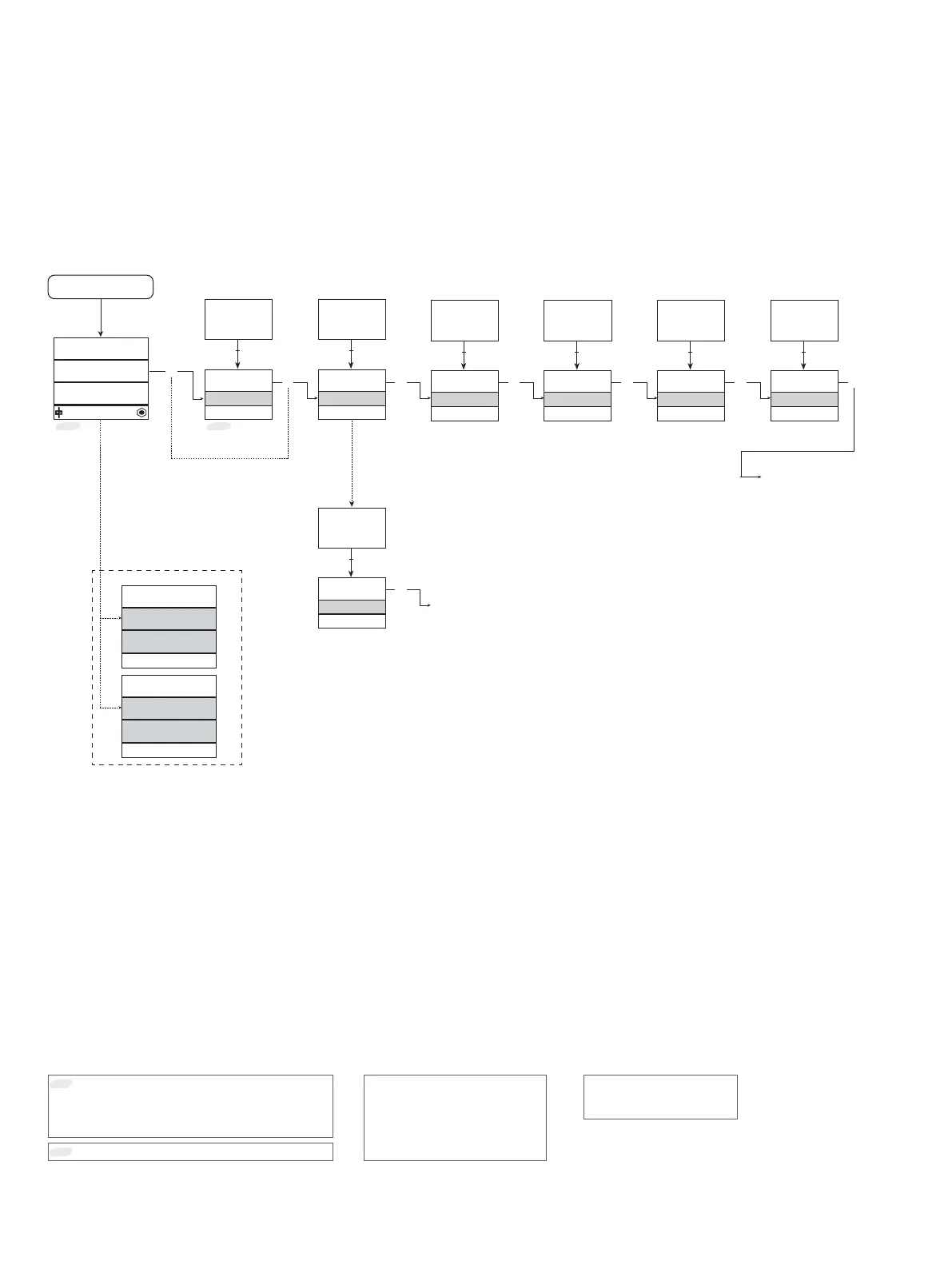
Routing diagram
If no key is activated for 1 minute, the display will return to the default state 1.0 without saving configuration changes.
1 Increase value / choose next parameter
2 Decrease value / choose previous parameter
3 Save the chosen value and proceed to the next menu
Hold 3 Back to previous menu / return to menu 1.0 without saving.
Continued on the page
Routing diagram ADV.SET
*1.0
Default state.
Line 1 shows status for channel 1 and channel 2.
Line 2 shows status for sensor 1.
Line 3 shows status for sensor 2.
Line 4 indicates whether the device is SIL-locked.
*1.1
Only if password-protected.
Line 1 symbols:
= OK. Flashing
= error.
Line 2 and 3 symbols:
Input frequency > 1 Hz =
Line 4 symbols:
Static dot = SIL-locked
Flashing dot = Not SIL-locked
Power up
Red text signifies safety
parameters in a SIL configuration.
See safety manual for details
To default
state 1.0
Error indication, examples