9202QI01
LERBAKKEN 10, 8410 RØNDE DENMARK
Revision date:
2016-04-07
Version Revision
V5 R0
Prepared by:
PB
Page:
3/3
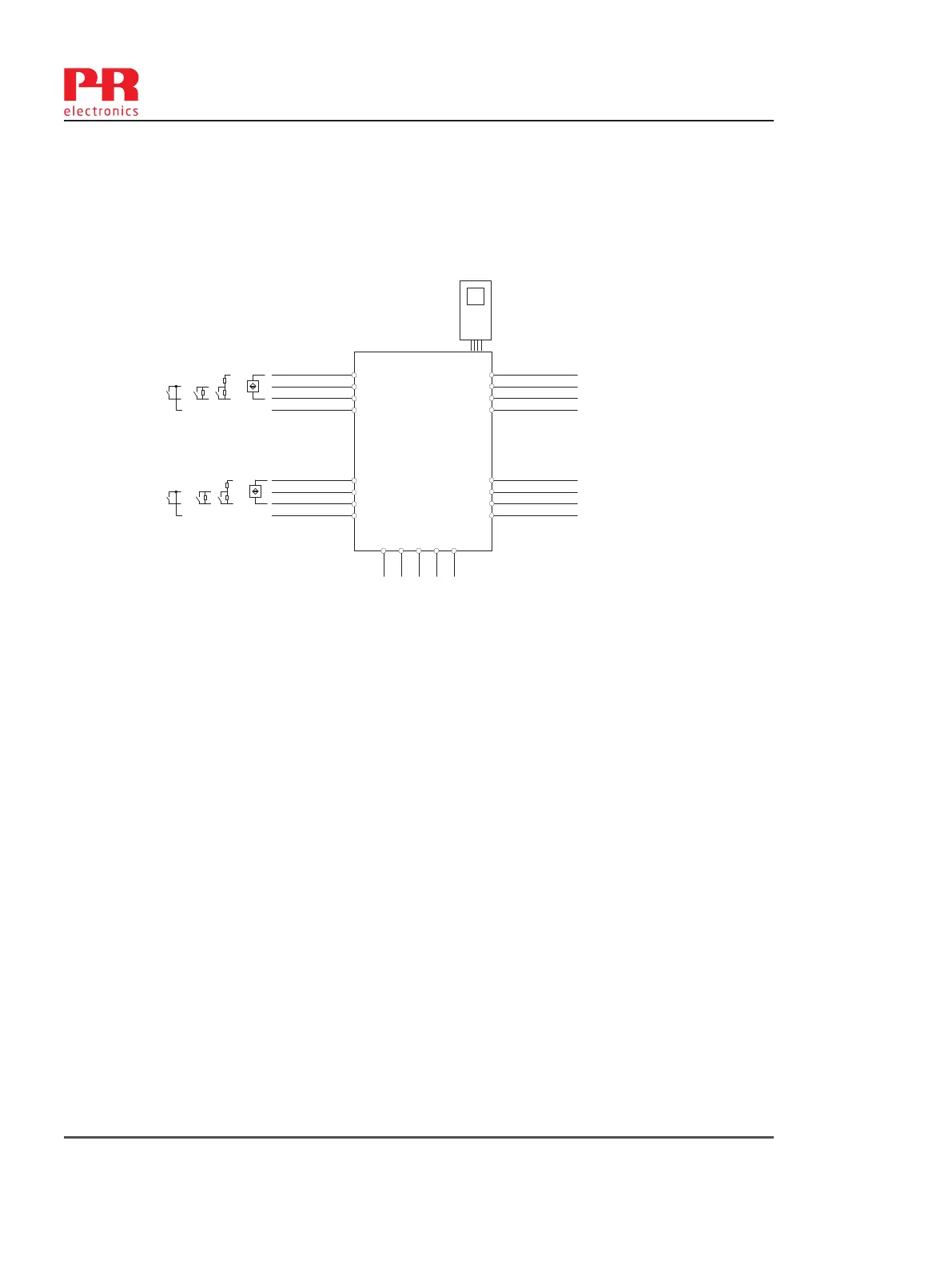
9202Axx Installation:
Non Hazardous area or Zone 2
Supply: 19.2 – 31.2 VDC
(terminal 31,32,33,34)
(terminal 91,92,93,94,95)
Input: Namur sensor, Contact Sensor, Switch
CH1 (terminal 41,42,43,44)
CH2 (terminal 51,52,53,54)
Output:
Terminal CH1(11,12) CH2(13,14)
Digital output: NPN output:
Voltage max. 30 VDC
Current max. 80 mA
Terminal CH1(11,12) CH2(13,14)
Relay output: Non Hazardous location Zone 2 installation
Voltage max. 250 VAC / 30 VDC 32 V AC / 30 VDC
Power max. 500 VA / 60 W 64 VA / 60 W
Current max. 2 AAC / 2 ADC 2 AAC / 2 ADC
For installation in Zone 2, the module shall be installed in an enclosure in type of protection Ex n or Ex e,
providing a degree of protection of at least IP54. Cable entry devices and blanking elements shall fulfill the
same requirements.
For installation on Power Rail in Zone 2, only Power Rail type 9400 supplied by Power Control Unit type 9410
(Type Examination Certificate IECEx 08.0052X) is allowed.
For Installation in Zone 2 / Division 2 the following must be observed.
The 4501 programming module is to be used solely with PR electronics modules. It is important that the
module is undamaged and has not been altered or modified in any way. Only 4501 modules free of dust and
moisture shall be installed.
-20 ≤ Ta ≤ 60ºC
44
43
42
41
54
53
52
51
34
33
32
31
14
13
12
11
9202
4501
91 92 93 94 95
Power
Rail
CH1
CH2
+
-
+
-
NAMUR Sensor
Switch
Switch w. Shunt
Contact Sensor
26 9202- Product version 9202-003