Do you have a question about the PR 9116 Series and is the answer not in the manual?
Temperature transmitters and intrinsically safe isolation barriers.
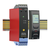
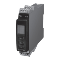
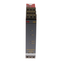
Interfaces for connectivity and devices for multiple applications.
High-quality isolators and devices for process value display.
Explanation of warning symbols like exclamation mark and CE mark.
Guidelines for handling hazardous voltages, receipt, unpacking, and environment.
Guidelines for connecting the device, emphasizing qualified personnel.
Procedure for detaching the device from the DIN rail.
Configuration, monitoring, simulation, and copying functionalities.
Use cases and environments, including hazardous zones.
LED indicators, galvanic isolation, and EMC immunity.
Details on RTD, TC, resistance, potentiometer, current, and voltage inputs.
Analog output (mA) and relay output specifications.
Connection requirements for the device's power supply.
Guides users through configuration with menu structure and help texts.
Interface for parameter modification and transferring configurations.
Step-by-step guide for attaching and removing the display front.
List of available accessories like display, connectors, and power units.
Environmental, mechanical, and electrical details of the device.
Details on power dissipation, required power, and isolation ratings.
General and basic accuracy values for different input types.
Specifications for RTD, linear resistance, and potentiometer measurement.
Supported Thermocouple types and their specifications.
Configuration and behavior of sensor error detection.
Signal range, load, stability, and error handling for current output.
Relay functions, hysteresis, delays, and error reaction settings.
List of directives like EMC, LVD, ATEX, and RoHS.
Details on DNV-GL, ClassNK, c UL us, EAC, and ATEX approvals.
SIL2 Certified & Fully Assessed acc. to IEC 61508.
How input signals outside the valid range are shown on the display.
Readout and conditions for sensor error detection (break/short).
List of hardware errors and their corresponding causes.
Diagrams for various input signal types: RTD, TC, resistance, potentiometer, current, voltage.
Diagrams for current output and relay output connections.
Diagram showing power rail connections for supply and status relay.
Schematic of internal connections for inputs, mA output, and relay output.
Mapping of LED status, relay status, and power rail status to conditions.
Guidance on navigating menus and using function keys for configuration.
How sensor errors and out-of-range signals are displayed.
LED indications for normal operation, supply issues, fatal errors, and sensor errors.
Description of different relay function settings like Setpoint, Window, Error, Power, Off.
Adjusting brightness, contrast, backlight, and TAG numbers.
Procedure for calibrating the device using two input points.
Setting a password to protect configuration against modifications.
Saving and transferring device configurations to other units.
How to adjust setpoints and test relay states during power up.
Illustrates how sensor error messages are displayed.
Diagram showing the flow for advanced settings.
List of selectable units for displaying process values.
Diagram showing different relay function settings.
Diagram illustrating configuration of output range and error actions.
Diagram for Memory, Display, Calibration, Simulation, Password, Language, Rail, SIL settings.
Detailed list of configuration parameters and their functions.
Parameters for calibration, system settings, and SIL configuration.
List of error codes, sensor errors, and communication issues.
Illustrates the window function with setpoints, hysteresis, and delays.
Illustrates the setpoint function with input signal, relay state, and delays.
References to IECEx, ATEX, and FM installation drawings.
Reference to the separate Safety Manual.
IECEx certificate, markings, and relevant standards.
Installation details for hazardous areas (Zone 0, 1, 2, 20, 21, 22).
Specifications for installing in Zone 2, including supply and relay terminals.
Intrinsic safety parameters for modules 9116B1 and 9116B2.
Electrical parameters for different terminal groups and hazardous area classifications.
Notes on installation for mines, pollution degree, and connector handling.
Diagram showing connection zones and temperature limits.
Wiring diagrams for supply, status relay, and relay output terminals.
Intrinsic safety and electrical parameters for 9116B 1/2 modules.
Wiring diagram for a 4-20 mA loop-powered transmitter.
Diagrams for terminal blocks, including status relay and relay output.
Electrical parameters for 9116B 1/2 modules and their groups.
Diagram showing connection zones and temperature limits for 9116Axx.
Wiring diagrams and specifications for 9116Axx installation.
ATEX certificate, markings, and relevant standards.
Installation details for ATEX hazardous areas.
Specifications for ATEX Zone 2 installation, including terminals.
Intrinsic safety parameters for ATEX modules 9116B1 and 9116B2.
Electrical parameters for different terminal groups and ATEX area classifications.
Notes on installation for mines, pollution degree, and connector handling.
Diagram showing connection zones and temperature limits for ATEX.
Wiring diagrams and parameters for ATEX installation.
Electrical parameters for ATEX modules 9116B 1/2 and their groups.
Wiring diagram for a 0/4-20 mA loop-powered transmitter.
Diagrams for terminal blocks, including status relay and relay output.
Electrical parameters for ATEX modules 9116B 1/2 and their groups.
Diagram showing connection zones and temperature limits.
Wiring diagrams and specifications for 9116Axx installation.
FM certificate and hazardous/unclassified location classifications.
Entity parameters for simple or intrinsic safe apparatus.
Specifications for FM Zone 2 installation, including terminals.
Intrinsic safety parameters for FM 9116B1 and 9116B2 modules.
Electrical parameters for different terminal groups and FM area classifications.
Notes on installation for Canada/USA, insulation, wiring, and safety warnings.
Diagram showing connection zones and temperature limits.
Wiring diagrams and parameters for FM installation.
Electrical parameters for FM modules 9116B 1/2 and their groups.
Wiring diagram for a 0/4-20 mA current source.
Diagrams for terminal blocks, including status relay and relay output.
Electrical parameters for FM modules 9116B 1/2 and their groups.
List of revisions and notes concerning document updates.
| Model | PR 9116 Series |
|---|---|
| Category | Media Converter |
| Data Rate | 10/100/1000 Mbps |
| Fiber Type | Single-mode or Multi-mode |
| Wavelength | 1310nm or 1550nm |
| Power Supply | 5V DC |
| Operating Temperature | 0°C to 50°C |
| Humidity | 5% |
| Ports | 1x RJ45, 1x Fiber |