Do you have a question about the PR 9116 and is the answer not in the manual?
Explanation of the meaning of various safety symbols.
Essential guidelines for safe installation and operation.
Glossary of key terms used within the manual.
Procedures for unpacking and checking the device upon arrival.
Recommended environmental conditions for device operation.
Instructions for the correct and safe installation of the device.
Procedures for calibrating and adjusting the device.
Guidelines for the safe and correct operation of the device.
Instructions for cleaning the device safely.
Information regarding product liability and warranty.
Step-by-step guide for safely removing the system.
Details on advanced functionalities and capabilities of the device.
Information on where and how the device can be used.
Specifications and technical details of the converter.
Visual representation of input and output signal wiring.
Diagram illustrating the power connection for the device.
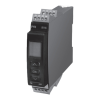
Description of the display and programming front's features and usability.
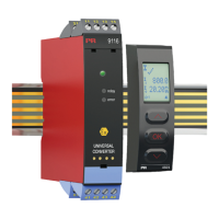
How the PR 4501 is used with the 9116 converter.
Detailed specifications of the PR 4501 display unit.
Instructions for attaching the PR 4501 to the 9116.
Codes used for ordering different versions of the 9116B.
List of available accessories for the 9116 product.
Detailed electrical parameters and ranges.
General specifications applicable to the device.
Information on accuracy based on input type and temperature.
Details on the device's immunity to electromagnetic interference.
Information on power supplies, dimensions, and weight.
Detailed input specifications for RTD, linear resistance, and potentiometer.
Specifications for Thermocouple (TC) inputs.
Details on CJC methods and accuracy.
Detailed parameters for current and voltage input signals.
Specifications for the analogue current output.
Specifics for the 2-wire current output.
Details on the available relay output functions and settings.
Parameters for the status relay output.
List of certifications and standards the device complies with.
Information on intrinsic safety and Ex certifications.
Details on the device's functional safety compliance (SIL).
How to configure sensor error detection.
How out-of-range input signals are displayed.
Limits for display readout below minimum and above maximum.
Information on how sensor errors are detected and indicated.
Table listing hardware errors, their readouts, and causes.
Explains the meaning of error indicators and how to acknowledge them.
Wiring for power rail and status/supply relay terminals.
Diagrams for various input signal connections.
Diagrams for current, 2-wire, and relay output connections.
A detailed block diagram showing internal connections and signal flow.
Table detailing LED and signal status for various error conditions.
How to use the device's function keys for configuration.
Information on setting and using passwords for configuration security.
How to select units for display and temperature measurements.
Options for Cold Junction Compensation setup.
How errors are displayed using the 4501 unit.
How errors are indicated using device LEDs.
Description of the different relay function settings.
Accessing and using advanced device functions.
Configuring display contrast and backlight.
Procedure for calibrating the device using two points.
Simulating input signals for testing.
Setting passwords and managing device configurations.
Choosing the display language for help texts.
Setting up sensor error transmission via the power rail.
Information and references for SIL compliance.
Diagram showing setpoint adjustment and relay test functions.
Flowchart for selecting input types and ranges.
Flowchart for selecting sensor and connection types.
Rules for navigating the routing diagram.
List of selectable units for display and measurements.
Detailed routing for configuring relay functions and parameters.
Routing for memory and display configuration.
Routing for password and language configuration.
Routing for calibration and power rail settings.
Routing for simulation and SIL configuration.
List of help texts for input and relay configuration options.
List of help texts for advanced settings like calibration and simulation.
Explains help texts related to errors and communication.
Visual representation of the window function for relay control.
Visual representation of the setpoint function for relay control.
References to installation drawings for various hazardous area certifications.
Reference to the separate safety manual.
Specific requirements for safe installation under IECEx certification.
Parameters for hazardous area installation and certifications.
Tables detailing electrical parameters for 9116B1 and 9116B2 modules.
Important notes for installing the module in hazardous environments.
Wiring diagrams for status relay and relay output terminals.
Electrical data tables for 9116B1/B2 modules.
Detailed electrical parameters for various module terminals.
Specific requirements for ATEX compliant installation.
Details on ATEX marking and hazardous area classifications.
Electrical parameters for modules under ATEX certification.
Important installation notes for ATEX compliance.
Requirements for safe installation according to FM standards.
Information on FM hazardous area classifications.
Electrical parameters for modules certified by FM.
Important installation notes for FM compliance.
Requirements for safe installation under INMETRO certification.
INMETRO hazardous area classifications and markings.
Electrical parameters for modules certified by INMETRO.
Important installation notes for INMETRO compliance.
Specifies the product versions covered by the safety manual.
Lists standards relevant to functional safety systems.
Glossary of acronyms and abbreviations used in the safety manual.
Explains the product's function and application in hazardous areas.
Conditions and limitations for using the product safely.
Operational and storage temperature, supply voltage, etc.
Accuracy requirements and minimum span for safe operation.
Limitations for TC types and sensor wiring considerations.
Procedures for managing sensor errors and ensuring safety.
Calibration procedures and output handling for safety.
Information on failure rates and safe configuration practices.
Guidelines for installing the device in hazardous areas.
How the device performs its safety function.
Compensation for cable resistance and CJC errors.
Specification of functions not related to safety instrumentation.
Safety parameters for various input types and outputs.
Safety parameters for current input signals.
General safety parameters like demand response time and SIL capability.
Information on the fixed hardware and software configuration.
Detailed failure rates categorized by input and output configurations.
Steps for performing periodic proof tests on the device.
Guidelines for repairing or replacing the product.
Information on required maintenance activities.
Reference to the routing diagram section.
Explanation of password protection for configuration.
How sensor and cable faults are shown on the display.
Introduction to the advanced functions menu.
Configuration options for memory, display, and password.
Settings for language, calibration, and power rail.
Settings for simulation and safety integrity level.
User's role in safe parameterization.
Table of common parameters like input type and range.
Options for selecting Pt sensor types.
Options for selecting Ni sensor types.
Options for TC sensor types and CJC.
Settings for sensor connection and resistance values.
Configuration for units, display values, and password.
Settings for relay units, functions, and contact types.
Configuration for relay setpoints, delays, and activation direction.
Settings for relay error actions and output delays.
Configuration for analog output range and error detection.
Setting output values for 0% and 100% and response time.
How to use and verify process calibration values.
Introduction to the device verification process.
Steps 1-6 for initial verification without a password.
Verifying input types, ranges, and sensor connections.
Steps 15-21 for verifying temperature units, sensors, and display settings.
Steps 22-28 for verifying relay settings and functions.
Steps 29-38 for verifying relay actions, delays, and output values.
Steps 39-41 for verifying password and SIL mode.
Steps for verification when a password is set.
Procedure for correcting parameters found to be incorrect.
How to perform a functional test after verification.
How the device reacts to faults and restarts.
Help texts for setting up input types, ranges, and sensors.
Help texts for configuring relay functions and parameters.
Help texts for advanced functions like calibration and simulation.
Help texts related to error codes, status, and communication.
Diagram showing power-up sequence and initial settings.
Flowchart for selecting input types and ranges.
Flowchart for selecting sensor and connection types.
Rules for navigating the routing diagram.
List of selectable units and their meanings.
Detailed routing for configuring relay functions and parameters.
Flowchart for configuring memory, display, and password.
Flowchart for calibration, simulation, and SIL configuration.
Wiring for power rail and status/supply relay.
Diagrams illustrating input terminal connections.
Diagrams for output terminal connections.
Overview of display products and Ex interfaces.
Overview of isolation products and temperature transmitters.
Description of universal programmable devices.
| Brand | PR |
|---|---|
| Model | 9116 |
| Category | Media Converter |
| Language | English |