24 9116 - Product Version 9116-003
@C
@F
K
%
m
cm
mm
um
ft
in
mils
yd
m3
l
s
min
m/s
mm/s
m/min
m/h
in/s
ips
ft/s
in/min
ft/min
in/h
ft/h
m/s2
rpm
Hz
t
kg
g
N
Pa
MPa
kPa
hPa
bar
mbar
kj
Wh
MWh
kWh
W
GW
MW
kW
hp
A
kA
mA
uA
V
kV
mV
ohm
S
uS
m3/min
m3/h
l/s
l/min
l/h
gal/min
gal/h
t/h
mol
pH
[blank]
Txt 9
3
100.0
DISP.HI
Txt 14
999.9
-199.9
1 2
3
DISP
REL.UNI
Txt 15
DISP
PERC
1 2
@C
UNIT
@C
@F
1 2
3
3
3
3
3
1.0= Defaultstate.Line1shows
input status. Line 2 shows
input value and TAG NO.
Line 3 shows output value
and units. Line 4 shows
status for relay and commu-
nication and whether the
device is SIL-locked. Static
dot=SIL-lockedand
flashingdot=notSIL-
locked.
1.1= Onlyifpassword-protected.
1.2= OnlyifFastSetisactivated
and the relay function is
setpoint.
1.3= Onlyifinputtypessupport
sensor error check.
Not valid for these input
signals: 0...20 mA and
voltage.
1.4= Onlyifinputsignalis
temperaure.
1.5= Onlyiftheconfigurationis
not protected by a pass-
word.
Continued on the next page
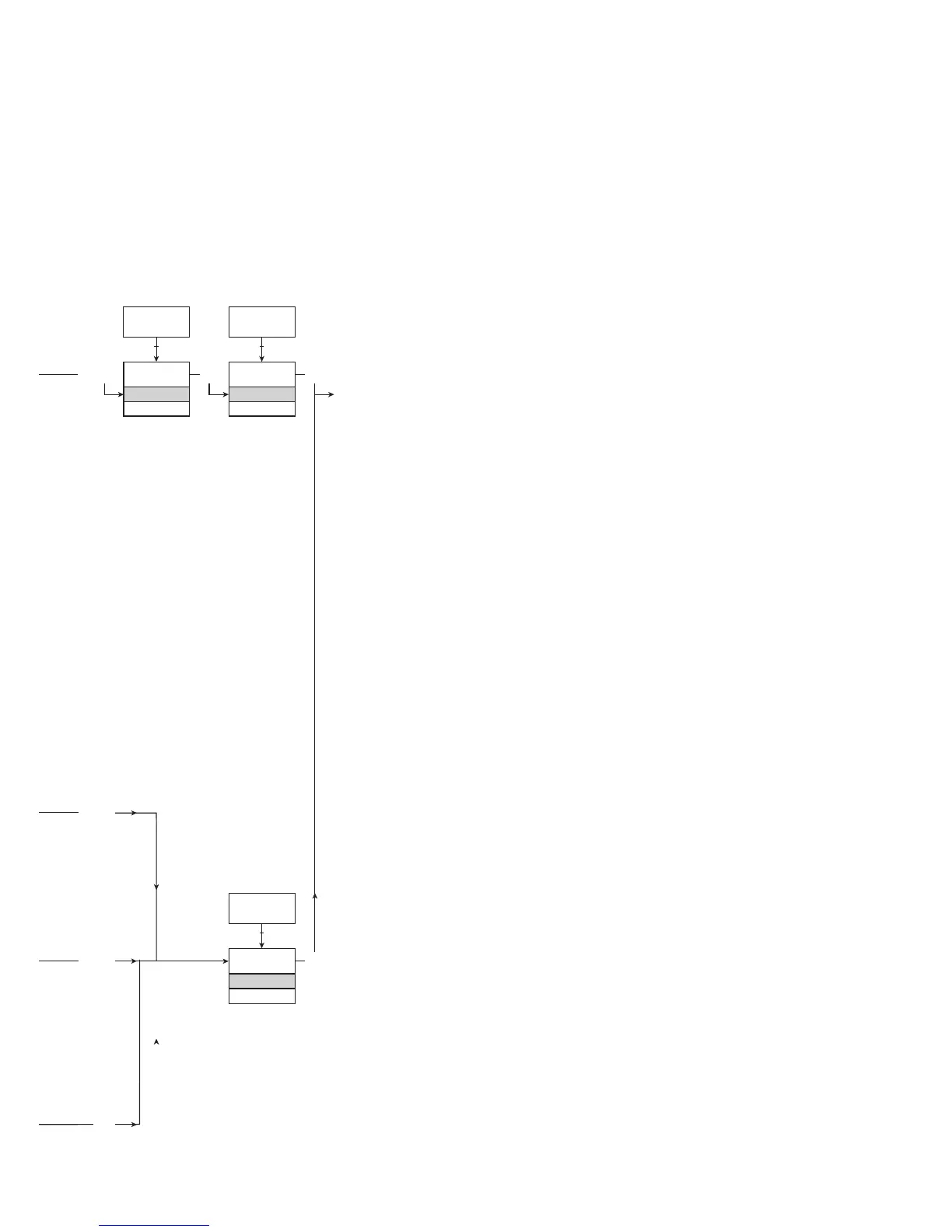
ROUTING DIAGRAM
If no key is activated for 1 minute, the display will return to the default state 1.0
without saving configuration changes.
1 Increase value / choose next parameter
2 Decrease value / choose previous parameter
3 Accept the chosen value and proceed to the next menu
Hold 3 Back to previous menu / return to menu 1.0 without saving
Selectable
UNITS: