1.0 = Default state. Line 1 shows
input status. Line 2
toggels between process
value and UNIT. Line 3
shows output and TAG No.
Line 4 shows status for
relay and communication
and whether the device is
SIL-locked. Static dot =
SIL-locked and flashing
dot = not SIL-locked.
1.1 = Only if password-protected.
1.2 = Only if FastSet is activated
and the relay function is
setpoint.
1.3 = Only if input types support
sensor error check.
Not valid for these input
signals: 0...20 mA and
voltage.
1.4 = Only if input signal is
temperaure.
1.5 = Only if the configuration is
not protected by a pass-
word.
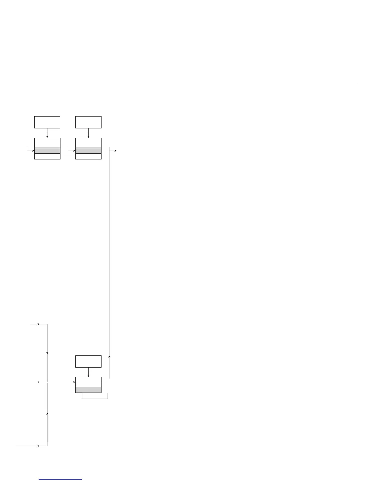
ROUTING DIAGRAM
If no key is activated for 1 minute, the display will return to the default
state 1.0 without saving configuration changes.
1 Increase value / choose next parameter
2 Decrease value / choose previous parameter
3 Accept the chosen value and proceed to the next menu
Hold 3 Back to previous menu / return to menu 1.0 without saving
Selectable
UNITS:
Continued on the next page