UNIK2E V2
ENGLISH
ISUNIK2Ev2_GB_02_09.doc
4
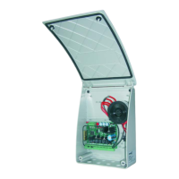
4. CONNECTION AND SET UP OF THE CONTROL UNIT
a) Before installing the UNIK2E control unit, read the “General safety warnings and notes” (page 13).
b) Fix the box using the special fixing holes.
c) Mount a differential thermo-magnetic circuit breaker 6A (IC=30mA) on the mains supply as specified in
the current reference standards (IC = differential current).
d) Place the supplied cable-ways and insert the cables keeping the power and supply cables separate from
each other.
e) Connect the external accessories making sure that the total of the average absorption of all the
connected accessories is less than the maximum current available (see info page 11).
f) ATTENTION: Connect the limit switches if present; otherwise do not jump inputs FC1, FC2, FO1
and FO2 in the terminal board.
g) ATTENTION: if there are no electrical limit switches and no mechanical stop in opening, proceed
as follows to define the manoeuvre times during learning:
• Press pushbutton 1 of the remote control or pushbutton P1/SET to stop the gate in the desired position.
• Press pushbutton 2 of the remote control or pushbutton P2/SET to stop the gate in the desired position.
h) Check the correct connection and operation of all the accessories connected to the terminal board.
NOTES:
INITIAL FACTORY SETTINGS
If there is no programming, the control unit will operate as follows:
• Step-step mode with automatic closing disabled.
• No slow-down
• Closing safety present
• No opening safety
• Obstacle detection trigger time (OBS) 1 second
• 3 second opening and closing time of the motors
• Safety test disabled
• Kick-back disabled
• Pushbutton 1 of transmitters enabled
• Rapid re-closing disabled
INITIAL SETTING OF THE TYPE OF OPERATOR
Check that the control unit is set for the application requested. When switched on, the red “RAD” LED flashes
for the number of times set in the control unit.
NUMBER OF FLASHES APPLICATIONS
1 Linear actuators
2 Operators with variable lever
(Variable absorption)
To modify the setting proceed as follows:
1. press the P2/RAD pushbutton until the corresponding red “RAD” LED lights up
2. press the P1/SET pushbutton, the control unit switches to another application
3. press the P2/RAD pushbutton again to exit the programming
4. The red “RAD” LED switches off to confirm that programming has been exited.
MOTOR POWER SUPPLY
The control unit adapts itself to run with motors of 12 or 24VDC according to the voltage with which it is
powered.
The UNIK2E control unit is fitted with a toroidal transformer with a 12VAC secondary.
Intelligent Security & Fire Ltd.
 Loading...