ENGLISH
27
9 PUMP INSTALLATION
9.1 Installation
The pump must be xed horizontally using the M12x1.5
threaded support feet. Tighten the screws with a torque of
80Nm.
The base must be perfectly at and rigid enough as not
to allow bending or misalignment on the pump coupling
axis/transmission due to torque transmitted during operation.
The unit cannot be xed rigidly to the oor but must
interposed with vibration dampers.
For special applications contact the Technical or Customer
Service Departments.
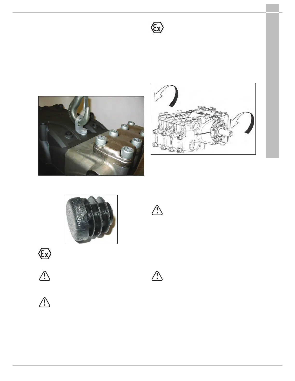
An M12 threaded stud is present on the pump casing, to
which an eyebolt can be applied to facilitate installation, as
per the gure below.
Should it be necessary to disassemble it, to avoid the entrance
of dirt in the front part of the casing, close the threaded hole
with the cap provided.
Earthing: the pump must be connected to an earth
conductor using the stainless steel M6 screw and
stainless steel serrated washer marked with a YELLOW
label. See “ATEX EXPLOSION PROTECTION” manual.
Replace the oil lling hole closing service
plug (red) positioned on the rear casing cover.
Checkthe correct quantity with the oil dipstick.
The oil dipstick must always be reachable,
evenwhen the unit is assembled.
The pump shaft (PTO) must not be rigidly
connected to the drive unit.
The following types of transmission are
recommended:
- Hydraulics by ange, for proper application
consult with our Technical or Customer Service
Departments.
- V-belts.
- Universal joint (comply with the maximum
working angles recommended by the
manufacturer).
- Flexible coupling.
In all cases the transmission must be assembled
correctly to avoid incorrect or harsh operation of
the connection parts and to prevent excessive
wear, temperature rise and/or hazardous breakages
that may create potential sources of ignition and
explosion. See “ATEX EXPLOSION PROTECTION”
manual.
9.2 Rotation direction
The rotation direction is indicated by an arrow located on the
casing near the dr
ive shaft.
From a position facing the pump head, the rotation direction
will be as in Fig.5.
LH SIDE
clockwise
RH SIDE
anticlockwise
Fig.5
9.3 Version change
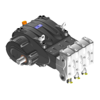
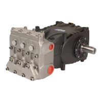
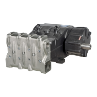
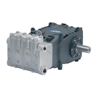
The pump version is dened as right when:
Observing the pump facing the head side, the pump shaft
must have a PTO shank on the right side.
The pump version is dened as left when:
Observing the pump facing the head side, the pump shaft
must have a PTO shank on the left side.
Note. The version shown in Fig.5 is right.
The version can only be modied by trained and
authorized personnel and carefully following the
instructions below:
1. Separate the hydraulic part from the mechanical
part as indicated in chapter2 par.2.2.1 of the
Repair manual.
2. Turn the mechanical part 180° and reposition
the rear casing cover in such a way that the
oil dipstick is turned upward. Reposition the
lifting bracket and relative hole closing plugs
in the upper part of the casing. Finally, properly
reposition the specication label in its housing
on the casing.
Make sure that the lower casing draining
holes in correspondence with the pistons are
open and not closed from the plastic plugs
provided for the previous version.
3. Unite the hydraulic part to the mechanical
part as indicated in chapter2 par.2.2.5 Repair
manual.



 To Next Page