ENGLISH
28
9.4 Hydraulic connections
In order to isolate the system from vibrations produced by
the pump, it is advisable to make the rst section of the duct
adjacent to the pump (both suction and outlet) with exible
piping. The suction hose must be suciently rigid to prevent
deformation due to the negative pressure exerted by the
action of the pump.
9.5 Pump supply
A positive head of at least 0.2 metres is required for the best
v
olumetric eciency.
For negative prevalence contact our Technical or
Customer Service Departments.
9.6 Suction line
For smooth operation of the pump, the suction line must have
the following char
acteristics:
1. Minimum internal diameter as indicated in the graph in
par.9.9 and in any case equal to or exceeding that of the
pump head.
Localized restrictions should be avoided along the
piping, as these can cause pressure drops resulting
in cavitation. Avoid 90° elbows, connections with
other piping, restrictions, reverse gradients, inverted
U-curves and Tee connections.
2. The layout must be such as to prevent cavitation
problems.
3. Completely airtight and constructed to ensure a perfectly
hermetic seal through time.
4. Prevent the pump from emptying when it is stopped,
including partial emptying.
5. Do not use 3 or 4-way hydraulic ttings, adapters, swivel
joints, etc. as they could jeopardize pump performance.
6. Do not install Venturi tubes or injectors for detergent
suction.
7. Avoid use of foot valves or other types of unidirectional
valves.
8. Do not recirculate the by-pass valve drain directly to the
suction line.
9. Provide for proper guards inside the tank to prevent that
water ow from the bypass and the tank supply line can
create vortexes or turbulence near the pump supply pipe
port.
10. Make sure the suction line is thoroughly clean inside
before connecting it to the pump.
9.7 Filtration
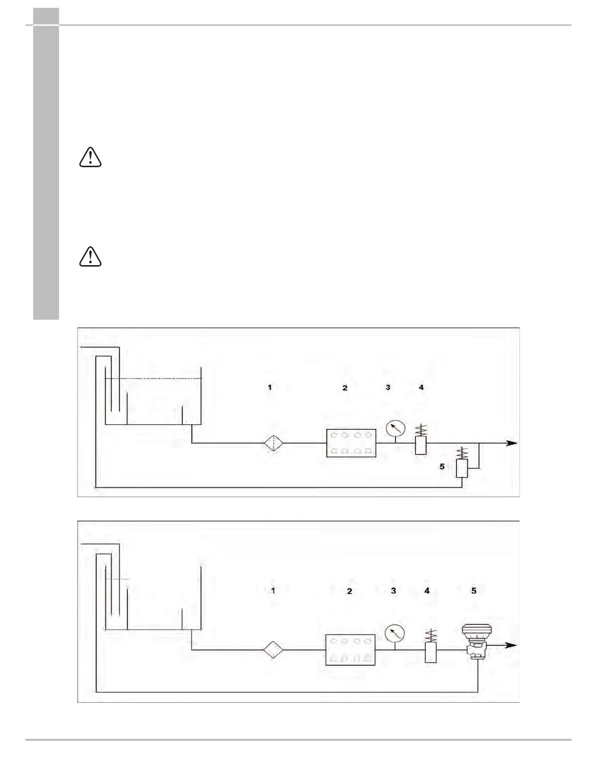
1 lter must be installed on the pump suction line, positioned as indicated in Fig.6 and Fig.6/a.
With a manually activated control valve
1 Filter 1
2 Plunger pump
3 Pressure gauge
4 Safety valve
5 Manual control valve
Inlet
Supply tank
Bypass
Fig.6
With pneumatic control valve
1 Filter 1
2 Plunger pump
3 Pressure gauge
4 Safety valve
5 Pneumatic control valve
Inlet
Supply tank
Bypass
Fig.6/a



 To Next Page