MW
44
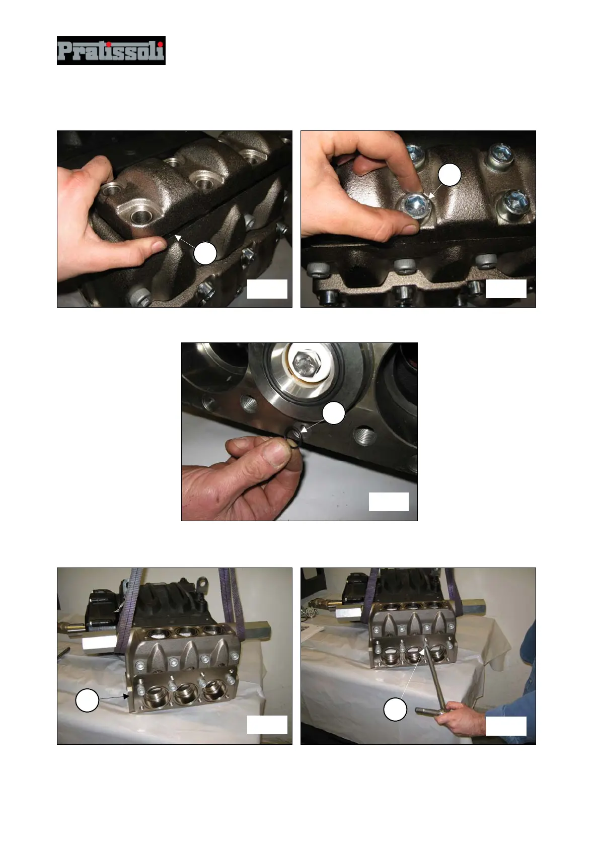
After having completed assembly of the outlet valve units, apply the outlet valve cover (pos.c, fig.160) and
screw in the 8 M16x45 screws (pos.c, fig.161).
Apply 6 front O-rings on the pump casing (pos.c, fig.162).
Assemble the pump casing head (pos.c, fig.163) taking care not to hit the pistons and screw in the 8
M16x150 screws (pos.c, fig.164).
Proceed with calibration of the M16x150 screws with a torque wrench as indicated in paragraph 3 "Screw
tightening calibration”.
fig. 160
1
fig. 161
1
fig. 163
1
fig. 164
1
fig. 162
1