20 www.PrecisionAerobatics.com
3 Copyrights ©2007 Precision Aerobatics. All rights reserved
Pre-Assembly
Before you commence assembling please inspect the contents of the kit for any damage that may have occurred during
transport or a suspected manufacturing defect. If you suspect any component is damaged please contact the shop from
which you purchased the model immediately. Do not commence the assembling of this kit.
We go to great lengths to ensure all components are manufactured free of warp or twist, however, due to high
temperatures on the long journey in a container and changes in humidity it is possible for small amounts of warp or twist
to develop. It is important at this stage to inspect for warp. Start by taping the ailerons in the neutral position at the wing
tip and look down the length of the ailerons to ensure they are perfectly straight. The ailerons should be neutral at the
wing tip (profile view), as they are at the wing root. If the aileron appears to be either deflected up or down at the tip
(known as wash-out or wash-in), it must be removed by gradually twisting in the opposite direction and carefully applying
heat to the wrinkles on the covering film (ideally with a hobby iron). Start at a very low temperature and gradually increase
until the wrinkles begin to shrink. Different films respond to heat in different ways and excessive heat will damage the
covering. Repeat this process until the aileron is perfectly straight with no twist visible. Do NOT use a heat gun as it
affects a much greater area which may cause an unwanted warp in other areas and burn the covering.
Inspect all sharp edges of the covering trims to verify they are sealed down. If there are loose edges that peel off, use an
iron to lightly seal them down, especially pay attention to wing and elevator tips (trailing edge & leading edge).
Place the elevator and rudder on a flat surface such a table top to ensure they are perfectly flat.
Ensure the elevator is not twisted by checking that both elevator counterbalances line up perfectly with the stabilizer
leading edge. If one counterbalance is slightly deflected up or down while the other side is neutral, the slight twist can be
removed in the same manner as the ailerons by gently twisting in the opposite direction and applying heat to the film
where it wrinkles. It is important to ensure that this step is completed prior to installing the stabilizer/elevator on the
model.
Any small bubbles or wrinkles in the covering film can also be removed with a small hobby iron, however extreme care
must be taken, as it is possible to introduce warp to an otherwise straight part while removing wrinkles. Start
at low temperature and gradually increase it. Use the iron front tip and only over the wrinkles to avoid warping other
areas! Avoid using a heat gun as it spreads the heat over a large area and can easily cause twists and warps.
Avoid keeping the hatch off the fuselage for long periods of time as it may develop some warp due to its length and
climate changes. Do not leave hatch/canopy out in the sun as it may warp as well.
Note: Through the manual - all left/right/rear indications are from pilot view
You may also watch "PA Build" videos available on our website, however, don't miss reading this instruction manual.
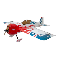
Making the Openings
Start by ironing around the edges of the openings to be made (excluding ailerons) to ensure the covering does not peel
back later. Next make the following openings in the covering film, as shown in the photos- elevator and rudder servos
(cutout one side only), cooling air exit, stabilizer slot and aileron servo bays.
Note: There are two identical sets of servo openings on each side of the fuselage. Choose the side per your preference.
Make sure to reveal the rudder and elevator control horn slots in the correct side of your servos final position.
The easiest way to make the openings is by ‘cutting’ the film with
the heated end of a paperclip (to heat use a cigarette lighter or a
candle) or with a very sharp modeling knife.
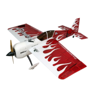
NOTE: finding the aileron servo bays through the opaque vinyl is
a bit challenging. The easiest method is to plug in the LED lights
into a battery and you’ll be able to identify the opening. Due to
the reflection avoid using direct flashlight.
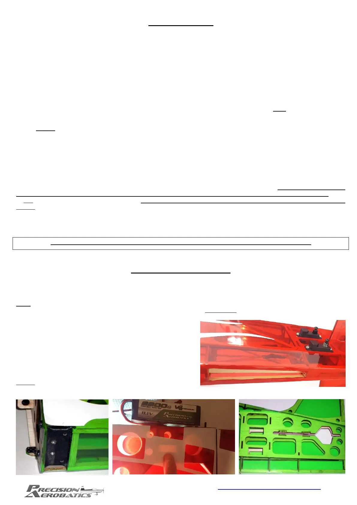
NOTE: Bottom wing square trims are made of high quality vinyl.
Do not apply heat as you may damage it.
 Loading...