20 www.PrecisionAerobatics.com
4 Copyrights ©2007 Precision Aerobatics. All rights reserved
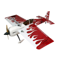
Aileron servo installation
Feed the cable through the inside of the wing out through the opening on the wing root rib. Insert the aileron servos with
the output shaft closest to the aileron. In case of tight fit don’t force the servo in, instead use a fine file to slightly enlarge
the opening.
Drill mounting holes as required for the screws supplied with your servos using a sharp 1.5mm (1/16”) drill bit. Ensure
that the screw holes are exactly centered. Use only fully threaded screws.
Do not use excessive force as this may damage the servo tray. Screw and unscrew the mounting screws and then apply
a drop of thin CA into each of the holes to set the thread. Once the CA has cured install the servo.
Tip: Carefully “tap” the screws in by making a full turn in and then backing out by ¼ turn and repeat until the screw sits
fully in.
Warning - we recommend not to use the rubber grommets and eyelets supplied with some servos as this method of
mounting will introduce excessive flex of the servo case under flight loads and will cause a loss of resolution in control
(“blowback” of the control surface). The best method is hard mounting of the servos (tail and aileron servos) with
aftermarket screws without the grommets and eyelets.
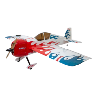
Find the four carbon fiber control horns and lightly sand the base of the horns to
allow better gluing surface. Expose the slots for the control horns. Since the
Addiction V2 has an opaque vinyl trim over one side of the slot, use a heated
paperclip or a modelling knife to reveal the slot through the top side of the wing
as it is easy to see the slot through the translucent covering. Test fit the CF horns. If the fit is too tight; do not force the
horn in. Instead, use a modeling knife to carefully enlarge the opening until a perfect fit is achieved.
With the servos centered in neutral, temporarily install the plastic servo arms. Find the best position of the servo arm
which yields 90 degrees to the servo case. That ensures linear and symmetrical throws in both directions without the need
of excessive TX sub-trims and servo travel adjustments to one direction. Once satisfied, cut off the other three unused
arms using a nail clipper or cutters.
In order to achieve maximum control throws for 3D and to ensure proper linkage geometry we recommend using PA
Carbon Fiber servo arms (PA Item Code AC-1913). Note that these are not included with the kit. If you have them, install
them now. You may wish to do so for the elevator and rudder servos at this point too.
Next, apply epoxy over the control horn base and inside the slots to glue the CF horns in and ensure that the horns were
inserted all the way in and are perfectly 90 degrees perpendicular to the control surfaces. There will be a bit of epoxy
excess once the control horns are slid into the slots. Do not wipe it off as it will create a solid base to the horns. IF needed,
use a piece of masking tape to hold the CF horns in position until the glue sets. Ensure adequate epoxy is applied to fill
up the holes at the base of the horns (once dry it acts as fixation pins).
Note: epoxy allows time for adjustment after the horns have been inserted while CA is prone to set too rapidly and may
also cause stains to the covering film.
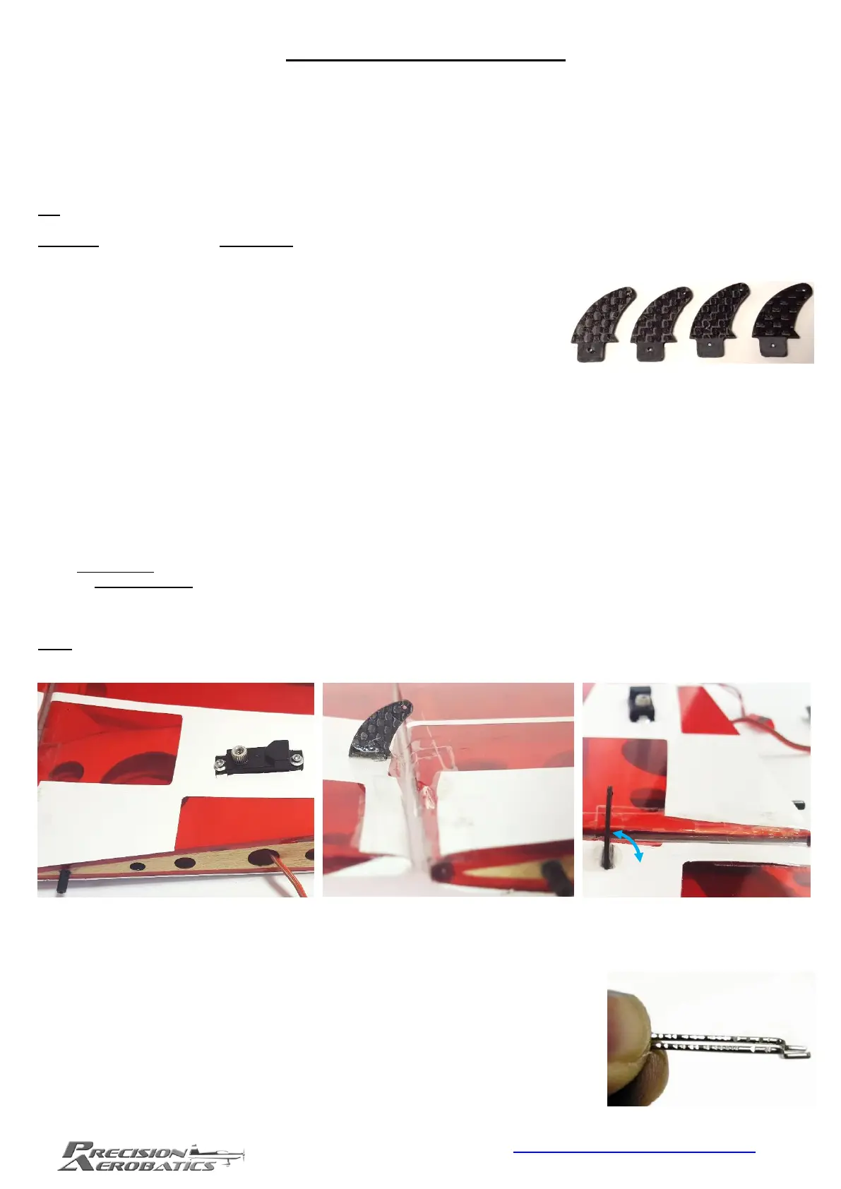
Once the epoxy sets, take the two identical aileron pushrods which are the shorter of the four supplied.
Lightly roughen and notch one end (+20mm/0.8”) of both CF pushrods using a Dremel
disk or small triangle file to ensure a secure glue bond. Do the same to the Z-bend
gluing surface, however, since it’s made of metal, you may choose to use a pair of wire
cutters to make a series of indentations but being careful not to cut through the wire.
Verify the Z-bends are free from any oil residue that will affect the integrity of the
gluing. Clean with alcohol if necessary.
 Loading...