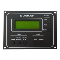
Precision Circuits Inc. One Place Monitor Panel
The Precision Circuits Inc. One Place Monitor Panel is a comprehensive control and monitoring system designed for recreational vehicles (RVs). It provides a centralized interface for managing various essential functions, including water pump operation, water heater control, generator status, battery levels, and tank levels. The panel is designed for ease of use with touch-sensitive buttons and a clear digital display.
Function Description
Water Pump Control:
The panel allows users to turn the water pump on and off with a simple touch. The display indicates the current status (ON or OFF). This function works in conjunction with a separate water pump control system and can display the pump's status regardless of where the physical switch is pressed in the RV.
Water Heater Control:
The panel offers control over both electric and LP (liquid propane) water heaters.
- Electric Water Heater: A touch-sensitive button toggles the electric water heater between ON and OFF. The display reflects the current status.
- LP Water Heater: A dedicated button controls the LP water heater. The display shows ON, OFF, or FAIL if the LP heater fails to ignite.
Generator Control and Monitoring:
The panel provides detailed information and control over the RV's generator.
- Meter Button: Touching the Meter button displays the generator's status (Running or Stopped) and its accumulated operating hours. This action only displays information and does not perform any control functions.
- Start Button: When the generator is stopped, pressing and holding the Start button will operate the generator starter, with the display showing "Starting." A brief touch of the Start button activates the Auto-Start function, causing the panel to attempt to start the generator automatically, indicated by "Auto-Start." If the auto-start fails, the display will show "Will Not Start."
- Stop Button: Pressing and holding the Stop button operates the generator stop relay, displaying "Stopping." If the generator is running, this will stop it. If the generator is stopped, this action will prime the fuel system. A brief touch of the Stop button activates the Auto-Stop function, causing the panel to attempt to stop the generator automatically, indicated by "Auto-Stop." If the auto-stop fails, the display will show "Will Not Stop."
Battery Level Monitoring:
Touching the "Battery Levels" button brings up a dedicated screen displaying the Chassis and House Battery Voltages. Both digital and analog (bar graph) formats are provided. The analog range is 10.0V-15.0V, with bar graph meter increments of 0.125 Volts. The screen updates every 1 second.
Tank Level Monitoring:
Pressing the "Tank Levels" switch displays the levels of various tanks. The screen updates every 1 second.
- Tank Types: The panel monitors Fresh Water, LP Gas, Gray Waste, and Black Waste tanks.
- Display Format: Levels are displayed in either 1/3's or 1/4's (E, 1/3, 2/3, F, or ERR; or E, 1/4, 1/2, 3/4, F, or ERR). "ERR" is displayed if a sensor exceeds normal limits.
- Multiple Waste Tanks: If the RV is equipped with extra waste tanks, the display splits into two screens, and touching the Tank Levels button toggles between them.
Important Technical Specifications
Power Requirements:
- The monitor panel requires between +11 Volts and +15 Volts between pins 2 and 5 of the J2 connector to be operational.
Water Pump Control Signals (J2 Connector):
- Voltage between pins 4 and 5: 2.5V when pump is off, 8V when pump is running.
- Momentary voltage near 0V when pump switch is pressed.
Water Heater Control Signals (J2 Connector):
- Electric Water Heater (pins 3 and 5): +12V when ON, 0V when OFF.
- LP Water Heater (pins 1 and 5): +12V when ON, 0V when OFF.
- LP Heater "FAIL" Indicator (pin 7): A +12V signal on pin 7 causes the display to read "FAIL."
Battery Voltmeter Signals (J2 Connector):
- House Battery (pins 2 and 5): Voltage should be close to House Battery Voltage.
- Chassis Battery (pins 8 and 5): Voltage should be close to Chassis Battery Voltage.
Tank Level Sensor Signals (J3 Connector):
- Each pair of wires for the 5 potential tanks should measure +5V when the Tank Level Button is pressed.
- Example for Fresh Water Tank: +5V from pin 6 (Ground) to pin 12 (Signal).
- Shorting the two pins together will display "ERR" on the screen.
LP Tank Sensor Specifications:
- Connector Removed (Ohmmeter between pins 1 and 7): Approximately 0 ohms when empty, 90 ohms when full.
- Connector Plugged In (Voltmeter between pins 1 and 7): 0 volts when empty, 2.25 volts when full.
Generator Control Signals (J1 Connector):
- Generator Running Indicator (pins 4 and 1): +12V when generator is running.
- Stop Button (pin 2): Voltage goes to 0V when pressed, returns to +12V when released.
- Start Button (pin 3): Voltage goes to 0V when pressed, returns to +12V when released.
Usage Features
Backlighting and Default Screen:
To conserve battery power, the backlighting will turn off after 1 minute of inactivity, and the display will return to the default "Water Pump" screen. However, the panel remains live and active.
Automatic Learn Features:
The panel incorporates three automatic learn features to adapt to the RV's configuration:
- Tank Sensor Type: Learns if water and waste tanks have 1/3 or 1/4 increment sensors.
- Multiple Waste Tanks: Detects if a second Gray and/or second Black Waste Tank exists.
- Water Heater Function: Identifies if a water heater function is present.
Each feature is learned independently and stored in non-volatile memory, retaining the information even if battery power is removed from the panel.
Tank Sensor Testing:
Individual tank sensor pads can be tested by placing a piece of sheet metal next to the top two sensors, which should change the display from 1/3 to 2/3.
Maintenance Features
Troubleshooting Guide:
The manual provides detailed troubleshooting steps for various issues, including:
- Non-operational panel: Checking power supply.
- Water pump indicator issues: Measuring voltage at the connector.
- Water pump not turning on: Measuring voltage when the switch is pressed.
- Water heater switch issues: Measuring voltage at the connector.
- Battery voltmeter inaccuracies: Measuring voltage at the connector.
- Water level sensor issues: Measuring voltage at the connector and testing individual sensor pads.
- LP tank issues: Measuring resistance and voltage at the connector.
- Generator function issues: Measuring voltage at the connector for running status and button presses.
Reset to Factory Default:
If the panel has incorrectly learned a feature, it can be reset to its original factory default settings, allowing it to re-learn the proper features. The reset procedure involves:
- Pressing and holding all three buttons (Water Pump, Tank Level, Battery Level) for approximately 6 seconds until the "Factory Mode" screen appears.
- Pressing the "Default" button (Water Pump).
- Pressing the "Exit" button (Battery Level).
- The panel will then return to the Water Pump display.