03/06/2012 Confidential and Proprietary Information
One Place Monitor Panel
Trouble Shooting Water Level Sensors
There is potentially up to 5 Tanks on the RV. Each one has a pair of wires going to the J3
connector.
When the Tank Level Button is pressed, and the Display is showing the levels of the
Tanks, each one of the 5 pairs of wires should measure +5V. For example for the Fresh
Water Tank there should be +5V from pin 6 Ground to pin 12 Signal.
Shorting the two pins together will display ERR on the screen. Shorting the two wires at
the tank will test those wires.
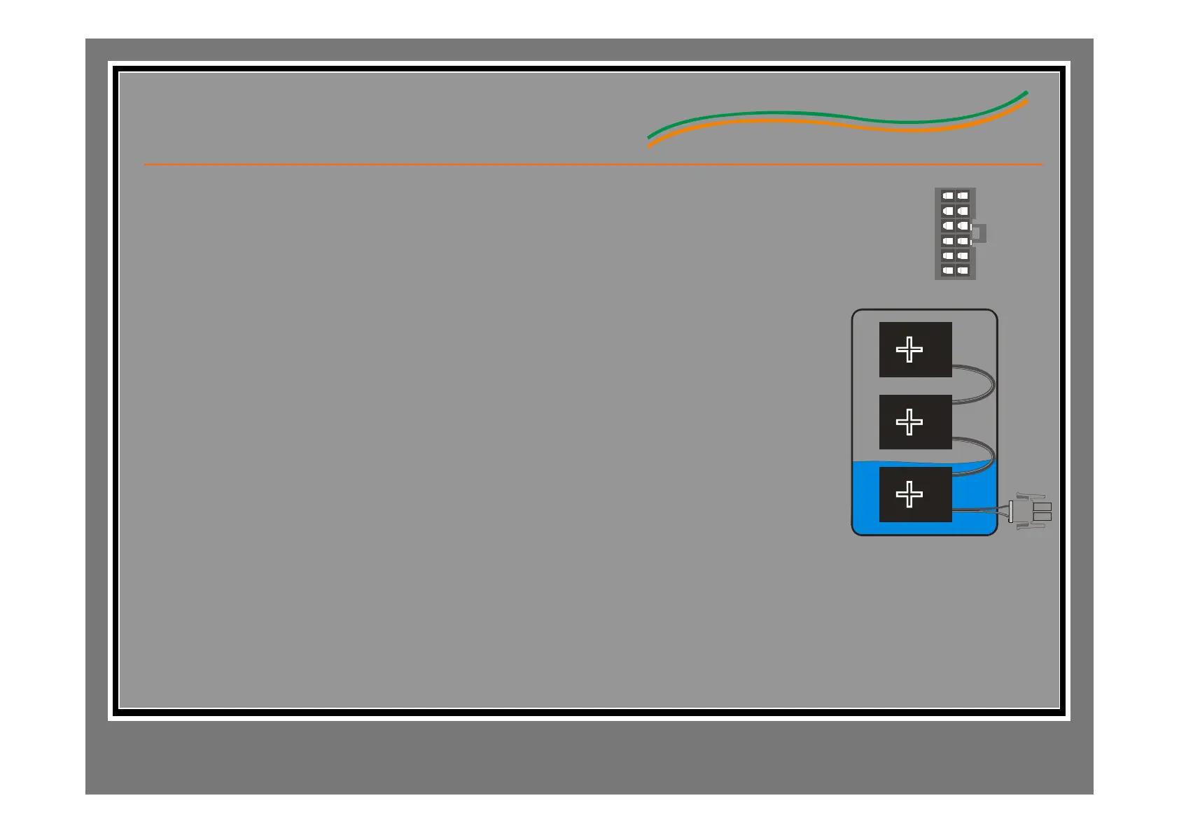
Each Sensor on the Tank will send a signal to the Monitor Panel when it senses water. In
the picture to the right, the bottom sensor pad should be sending a signal. Placing a
piece of sheet metal next to either of the top two sensors should change the display from
1/3 to 2/3. In this way each individual sensor pad can be tested.
Trouble Shooting LP Tank.
Unplugging the connector from the board (or an open connection to the LP Tank Sensor)
will produce an ERR display.
With the connector removed from the Panel, place an ohm meter between pins 1 and 7 of
the connector. The LP sensor should measure approximately 0 ohms when empty and 90
ohms when full.
With the connector plugged in, place a Voltmeter between pins 1 and 7 of the connector.
The voltage reading should be 0 volts when empty and 2.25 volts when full.
GRAY TANK 2 GROUND
BLACK TANK 1
LP SEN SOR
FR ESH TA NK GROU ND
BLACK TANK 1 GROUND
LP SE NS OR GROUND
BLACK TANK 2 GR OU ND
GRAY TANK 1 GROUND
BLACK TANK 2
GRAY TANK 1
GRAY TANK 2
FRESH TANK
56 4 3 2 1
1112 8 7
Tank
Sensor
Module
To Monitor