22
PM-1030V v5 2020-10 Copyright © 2020 Quality Machine Tools, LLC
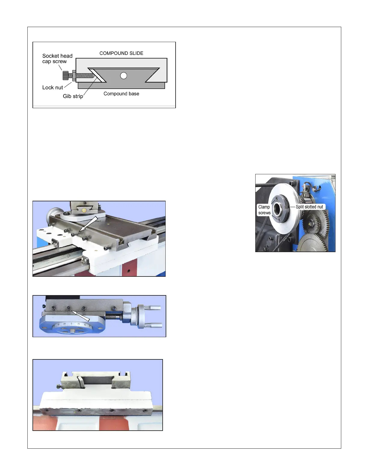
ADJUSTMENT — GIB SCREWS
The cross-slide and compound slide on ground dovetail ways,
Figure 4-8. In the gap between inner and outer dovetails is a
thin strip of cast iron, the gib strip. Screws with locknuts on the
sliding component press the gib strip rmly against the inner
dovetail, eliminating unwanted side to side movement while at
the same time allowing smooth positioning by leadscrew and
handwheel. Adjusting the gib screws is a trial and error process
that takes time and patience. Aim for the best compromise of
rigidity and reasonably free slide motion. Too tight means ac-
celerated wear on the ways and leadscrews. Too free means
instability of the cutting tool, inaccuracies and chatter.
Figure 4-8 Gib strip schematic
Figure 4-9 Cross-slide gib screws (four)
Arrowed screw is the lock screw
Figure 4-11 Saddle gib support
The saddle gib is not adjustable
Figure 4-12 Spindle nut
Figure 4-10 Compound gib screws (three)
Arrowed screw is the lock screw
ADJUSTMENT — CROSS-SLIDE BACKLASH
When alternating between clockwise and counter clockwise
rotation, the cross-slide handwheel may move freely a few de-
grees but the cross-slide table stays put.
Cross-slide lost motion is due to two factors: 1. Too-loose at-
tachment of the handwheel attached to the leadscrew, and;
2. Wear in the leadscrew nut, item #32 in the parts diagram,
page 30. This is a split nut that is adjustable by M4 screws,
item #39.
ADJUSTMENT — SPINDLE BEARINGS
The spindle runs on two grease-packed tapered roller bear-
ings. They are factory adjusted, and should need no attention.
If end play becomes evident (workpiece chatter, poor nish,
etc.), this can be corrected by tightening the slotted nut se-
curing the Vee pulley, Figure 4-12. To do this, loosen the two
clamp screws, then gently tighten the slotted nut using a soft
metal drift and hammer. Don't overdo this! Over-tightening can
damage the bearings. Re-tighten the clamp screws.
 Loading...


