13
PM-1236 v4 1-2017.indd
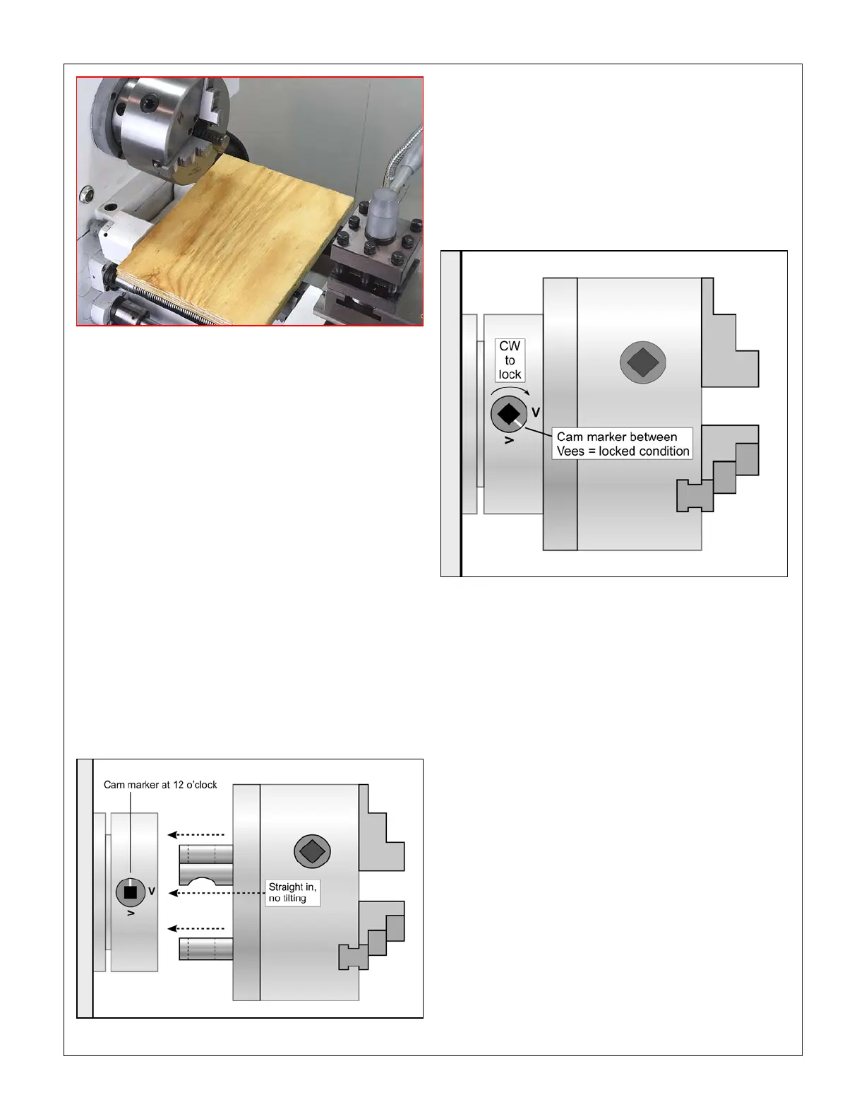
Figure 3-7 Installing a Camlock chuck
Figure 3-6 Protect the lathe bed
a “between teeth” condition to disengage the gear
train.)
Turn the spindle by hand, checking that all three cam
markers are at 12 o’clock.
While supporting its full weight, install the chuck
without tilting, see Figure 3-7, then gently turn each
of the cams clockwise — snug, firm, but not locked
in this first pass.
Check that each of the cam markers lies between 3
and 6 o’clock, between the two Vees stamped on the
spindle, Figure 3-4.
If any cam marker is not within the Vees, first be sure
that there is no gap between chuck backplate and
spindle flange. Also, remove the chuck to inspect the
studs — burrs can be a problem, hone if necessary.
If there are no visible problems, the stud in ques-
tion may need adjustment as follows:
Remove the stop screw from the stud.
If the cam marker in question can’t get to the first
Vee (3 o’clock), back the stud OUT one full turn, then
2.
3.
4.
5.
•
•
replace the stop screw.
If the cam marker goes beyond the second Vee (6
o’clock), screw the stud IN one more turn, then re-
place the stop screw.
If the markers are correctly aligned, repeat the tight-
ening sequence as step 3, light force. Repeat the
sequence two more times, first with moderate force,
then fully tighten.
•
•
Figure 3-8 Cam in locked condition
TO REMOVE A CHUCK
Disconnect the 220V supply from the lathe!
Protect the lathe bed, as Figure 3-6. While supporting its
weight, turn each of the cams to 12 o’clock, Figure 3-7,
then remove the chuck. If the chuck does not come free,
try tapping the backplate gently with a soft (dead blow)
mallet.
CROSS SLIDE AND COMPOUND
The cross slide and compound, Figure 3-9, both have
10 TPI leadscrews, with 100-division graduated collars,
so each division represents a “real” motion of 0.001”. On
the cross slide dial, only, this shows as ϕ 0.002”, mean-
ing that a 0.001” depth of cut reduces the diameter of
the workpiece by 0.002”. The second row of divisions on
each collar reads in millimeters, 0.02 mm/division on the
compound, 0.04 mm/division on the cross slide. [These
collars have 127 divisions, so the reading is “true met-
ric”.]