10PM-1440BV v3 2020-10 Copyright © 2020 Quality Machine Tools, LLC
T S R U T S R U
A D
0.0187 0.0175 0.0140 0.0112 0.0094 0.0087 0.0070 0.0056
B D
0.0094 0.0087 0.0070 0.0056 0.0047 0.0044 0.0035 0.0028
A C
0.0047 0.0044 0.0035 0.0028 0.0024 0.0022 0.0017 0.0014
B C
0.0024 0.0022 0.0017 0.0014 0.0012 0.0011 0.0009 0.0007
ENGAGING THE POWER FEED
(For normal turning and facing operations)
To activate the feed shaft: 1. Set the Saddle Feed direction
lever, Figure 3-1 (4), to the left, and; (2) Set the upper right
knob on the gearbox to 0 (selections 1-2-3-4 are used only for
thread cutting with the leadscrew).
The power feed lever on the apron, Figure 3-4, is active only
when the feed shaft is rotating (the split-nut lever engages
the leadscrew).
When engaging power feed, move the lever gently, feeling
for the gears to mesh as you go. If the gears don’t engage at
the rst try, use the appropriate handwheel to jog the saddle
or cross slide, whichever one you wish to move under power.
The rate of power feed relative to spindle speed is set by se-
lector knobs on the gearbox, together with external change
gears on the end face of the headstock, Figure 3-3. Two pair-
ings are commonly used: 60T upper/60T lower, and 30T up-
per/60T lower. Feed rates are listed in Figure 3-5.
Figure 3-5 Power feed rates (inches per spindle rev)
For any given change gear and gearbox selection, sad-
dle motion is approximately 3 times cross-slide motion.
T S R U T S R U
A D
0.0548 0.0512 0.0411 0.0328 0.0274 0.0256 0.0205 0.0164
B D
0.0274 0.0256 0.0205 0.0164 0.0137 0.0128 0.0102 0.0082
A C
0.0137 0.0128 0.0102 0.0082 0.0069 0.0064 0.0051 0.0041
B C
0.0069 0.0064 0.0051 0.0041 0.0034 0.0031 0.0025 0.0020
SADDLE FEED
Inches/spindle revolution
CROSS SLIDE FEED
Inches/spindle revolution
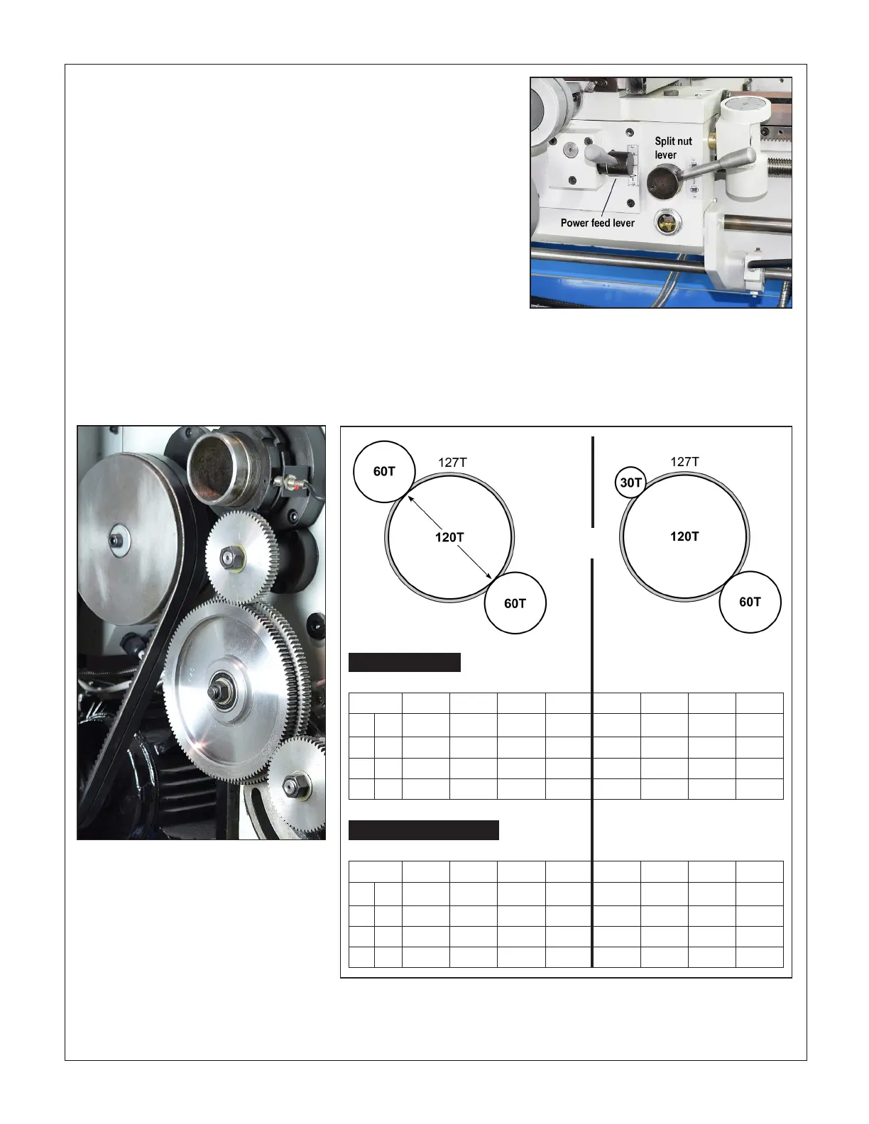
External gears
Figure 3-4 Feed control levers on the apron
To power the saddle (longitudinal motion), move the power feed lever
to the RIGHT, then UP, as shown here. To power the cross slide, move
the lever LEFT and DOWN. Test for engagement/dis-engagement by
gently jogging the saddle and cross-slide handwheels. The split nut le-
ver, used only for thread cutting, cannot be engaged unless the power
feed lever is NEUTRAL, neither up or down.
Figure 3-3 External change gears
This is the same setup used for U.S. thread
cutting (see later in this section). Shown
here are 60T upper, 60T lower — the same
pairing used for threads such as 20 and 32
TPI. The other pairing recommended for
power feed, 30T upper/60T lower, is also
used to cut 24 and 48 TPI threads.
ALTERNATIVE GEAR ARRANGEMENTS
Small change gears can be installed with the hub facing out,
as Figure 3-8, lower gear. For the upper change gear, only,
this does not apply to gears larger than 42 teeth.

 Loading...

