22PM-1440BV v3 2020-10 Copyright © 2020 Quality Machine Tools, LLC
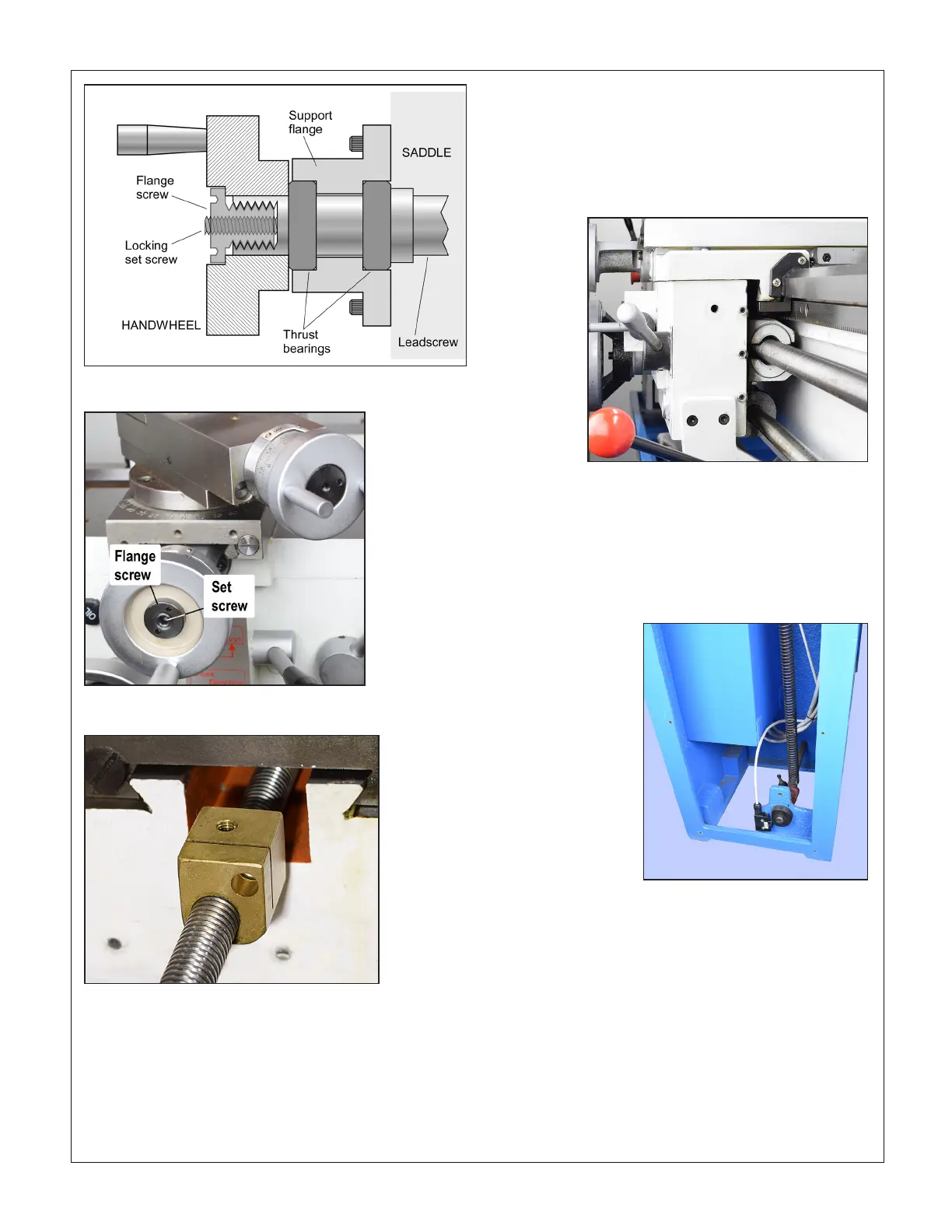
Figure 4-14 Cross slide leadscrew nut (representative)
FOOT BRAKE
There is no physical brake in the drive train. Instead, when the
treadle-operated switch (Figure 4-16) opens, the VFD disables
the motor drive and dumps motor power to a braking resistor,
see Section 5 electrical schematic.
SPLIT NUT ADJUSTMENT
In thread-cutting operations, if the split nut becomes exces-
sively loose — appreciable side to side movement — this may
be corrected by adjusting the gib at the right side of the apron.
Remove the threading dial, then tighten the three gib screws
as necessary, Figure 4-15. Over-tightening can make disen-
gagement of the split nut dicult.
Figure 4-15 Split nut gib screws
Figure 4-16 Foot brake switch
Figure 4-13A Handwheel attachment schematic
Figure 4-13B Handwheel attachment