5PM-1440BV v3 2020-10 Copyright © 2020 Quality Machine Tools, LLC
INITIAL CHECKS
Read Section 3 if unsure about any item in this list
Do not change speed while the motor is running
BEFORE connecting power, do the following:
1. Visually check the entire machine for possible distur-
bance in shipping, including the motor, Vee belts and
external gears under the belt cover left of the headstock.
Replace the belt cover.
2. Check oil level (sight glasses) in the headstock, the
saddle feed gearbox, and the apron. See Section 4.
3. If a chuck or faceplate is installed, check tightness of the
six Camlocks on the spindle nose, Section 3.
4. Set the speed gear lever to L (low). Make sure the gears
are properly meshed by “jiggling while shifting” — ro-
tate the chuck back and forth by hand while moving the
levers into position. Make certain that the motor control
lever is set to OFF, mid-travel, Figure 1-7.
5. Set the speed control knob fully counter clockwise (slow-
est speed).
6. Set the Feed Direction knob to its center (neutral)
position, Figure 1-8.
7. Check that there are no clamps or locks on moving parts.
8. Check that the footbrake treadle is released (UP).
9. Set the saddle and cross slide to approximate mid-travel.
10. Connect and switch on 220 Vac power (switch located
at back of headstock). The tachometer display (spindle
speed), Figure 1-8, should light, unless a circuit breaker
in the electrical box has tripped.
11. Be sure the Emergency Stop (E-Stop) button has not
been pushed in (it should pop out when twisted clock-
wise).
12. Shift the motor control lever DOWN. Turn the speed
control knob a few degrees clockwise to run the motor
at low speed. The spindle should turn Forward, counter
clockwise, viewed at the chuck (nose) end. The control
system can be rewired for DOWN = Reverse, see below.
13. Check the emergency function by pressing the E-Stop
button. The motor should stop. If this doesn’t happen,
the E-stop function is defective, and needs attention.
14. Reset (twist) the E-Stop button to restore power.
15. Check that the footbrake stops the motor.
16. Return the motor control lever to OFF, mid-travel.
17. Shift the motor control lever UP. The spindle should
Reverse, clockwise rotation, viewed at the chuck (nose)
end. The control system can be rewired for UP = Forward, see
below.
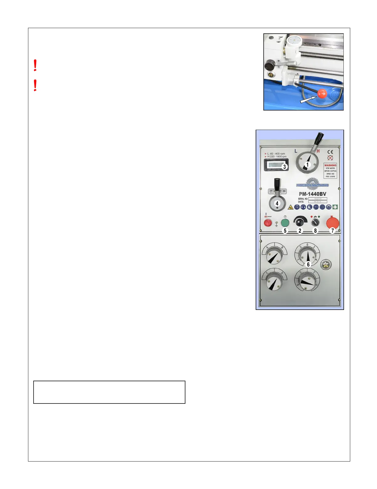
Figure 1-7 Motor control lever
REVERSING THE MOTOR CONTROL LEVER
See electrical box photo, page 27
Figure 1-8 Front panel
controls
(1) Speed range selector
(2) Speed adjust knob
(3) Tachometer display
(4) Feed direction lever,
shown here in neutral
(5) JOG push button, runs
the spindle forward a few
degrees when pressed
(or backward if the motor
control lever has been
re-directed)
(6) Feed gearbox control,
one of four; only the feed
shaft is driven (not the
leadscrew) when this knob
is set to 0
(7) E-Stop button. Disables
the machine when pressed;
twist (pops out) to restore
power
(8) Coolant ON/OFF
OPTIONAL TEST RUN PROCEDURE
Run the spindle for a few minutes, forward and reverse, at
various speeds.
If desired, the saddle feed gearbox may also be run at this
time, but rst make certain that all components aected have
been lubricated, then exercise the saddle and cross slide man-
ually before power-feeding — see Section 3 for power feed
directions.
Precision Matthews recommends draining and relling all
three gearboxes (Headstock, Saddle Feed and Apron) af-
ter approximately 20 hours of initial run time. Lubricants
are specied in Section 4.
ALIGNING THE LATHE
The most important attribute of a properly set up lathe is its
ability to “machine parallel”, to cut a cylinder of uniform diame-
ter over its entire length. In other words, no taper.
Leveling of the lathe is a part of this, see earlier in this section.
Equally important is the alignment of the center-to-center axis
with the lathe bed, as seen from above. [Vertical alignment is
nowhere near as critical, rarely causing taper unless the lathe
is damaged or badly worn.] For more information see the nal
pages of Section 4, Servicing the Lathe.

 Loading...

