11PM-1440BV v3 2020-10 Copyright © 2020 Quality Machine Tools, LLC
FEEDSHAFT CLUTCH
The clutch shown in Figure 3-7 disengages the power feed if
the saddle or cross slide hits an obstruction when power feed-
ing, thus minimizing the potential for damage. This could be
the result of either an accidental event, or deliberately stopping
the saddle at a precise location set by the saddle stop, Figure
3-6.
The clutch comprises a pair of spring loaded steel balls bear-
ing on a detent disc driven by the saddle feed gearbox. Spring
pressure is adjusted by two set screws on either side of the
feed shaft, arrowed in Figure 3-7. Setting the spring pressure
is a process of aiming for the best compromise between too
high — damaging feed pressure — and too low, stopping pre-
maturely.
Setting the clutch to work reliably with the micrometer carriage
stop is a good example of such a compromise: start with low
spring force, then work up in small increments until the car-
riage stops in the same location (say ± 0.002”, assuming a
constant depth of cut and feed rate).
SADDLE STOP
The stop assembly, Figure 3-6, has a micrometer-style collar
graduated in 0.001 in. divisions. It can be clamped at any point
along the lathe bed (two M6 socket head screws on the under-
side secure the clamp plate to the block).
Figure 3-6 Saddle stop (representative)
Figure 3-7 Feedshaft clutch
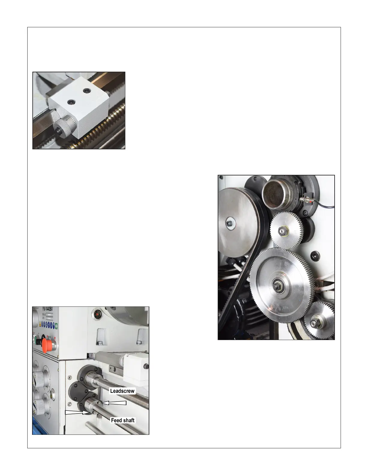
THREAD CUTTING
External change gears
The large gears in Figures 3-3 and 3-8 are transposing gears,
120T and 127T. They allow a standard-thread leadscrew, in
this case 8 TPI, to cut metric threads. The transposing gears
are cut from a single steel blank.
KEY FACTS TO REMEMBER ...
TPI threads
See Figure 3-3. For inch thread cutting, the 120T smaller gear
is simply an idler, transferring the drive from the upper change
gear to the lower change gear.
Metric threads
The upper change gear engages the 127T gear, Figure 3-8.
The smaller of the transposing gears, 120T, drives the lower
change gear.
For metric threads the split-nut on the apron must be left
engaged throughout the entire process.
Figure 3-8 External gear setup for metric threads
The lower change gear is installed hub outward.
METRIC vs. U.S. THREAD SETUPS
The 127T/120T transposing gear is installed 127T to the out-
side for metric threads, 120T out for U.S. threads. This calls
for reversal of the gear’s ball bearing assembly — two ball
bearings on a shouldered bushing. The bushing has to be
tapped clear of the ball bearings, then re-installed the other
way around.
A time-saving suggestion: Remove the shouldered bushing
and part-o the larger diameter portion. Re-install the smaller
diameter in the ball bearings. For the removed portion substi-
tute a separate plain collar. This will allow the transposing gear
to be installed either way with no additional eort.

 Loading...

