12PM-1440BV v3 2020-10 Copyright © 2020 Quality Machine Tools, LLC
Gear shifters
R-1 U-1 U-1 U-1 U-1 U-1 T-1 U-1 U-3
er
gear
60 60 60 60 40 40 30 40 60
er
gear
60 54 57 60 44 46 60 52 63
A-D 4 4-1/2 - 5 5-1/2 - 6 6-1/2 7
B-D 8 9 9-1/2 10 11 11-1/2 12 13 14
A-C 16 18 19 20 22 23 24 26 28
B-C 32 36 38 40 44 46 48 52 56
Figure 3-9 Threads per Inch (TPI)
Gear swapping
Any change to the drive train typically calls for one or both
of the upper and lower gears to be exchanged for a larger or
smaller gear. This will require the transposing gear pair to be
repositioned. The procedure for this is:
1. Use a 18 mm wrench to remove the hex nuts from the up-
per and lower gear shafts.
2. Remove the gears, washers, keys and bushing (lower gear
only).
3. While holding the gear support casting (quadrant) with one
hand, use a 16 mm wrench to loosen its anchor nut. Allow
the casting to swing downward.
4. Loosen the 16 mm hex nut securing the transposing gears
to the support casting.
5. Install the lower gear (for TPI threads the 120T gear is out-
side, for metric threads, inside).
6. Bring the transposing gears into mesh with the lower gear,
trapping a scrap of bond paper (letter stock) between the
two to hold them at the correct separation.
7. Tighten the transposing gears in position, then remove the
paper. Check for working clearance between the gears.
8. Install the upper gear.
9. Swing the gear support casting upward to mesh the 127T
gear with the upper gear, again using a paper scrap for
separation.
10. Tighten the gear support casting.
11. Lubricate the gears.
Gear shifters
R-4 U-4 S-3 T-4 U-1 R-3 T-1 U-3 U-1
er
gear
56 60 60 30 60 60 30 60 42
er
gear
60 60 60 60 60 60 60 60 63
A-D 7.0 6.0 - 5.0 - 4.5 4.0 - -
B-D 3.5 3.0 - 2.5 - 2.25 2.0 1.8 1.6
A-C 1.75 1.5 1.4 1.25 1.2 - 1.0 0.9 0.8
B-C - 0.75 0.7 - 0.6 - 0.5 0.45 0.4
Figure 3-10 Metric thread pitches (mm)
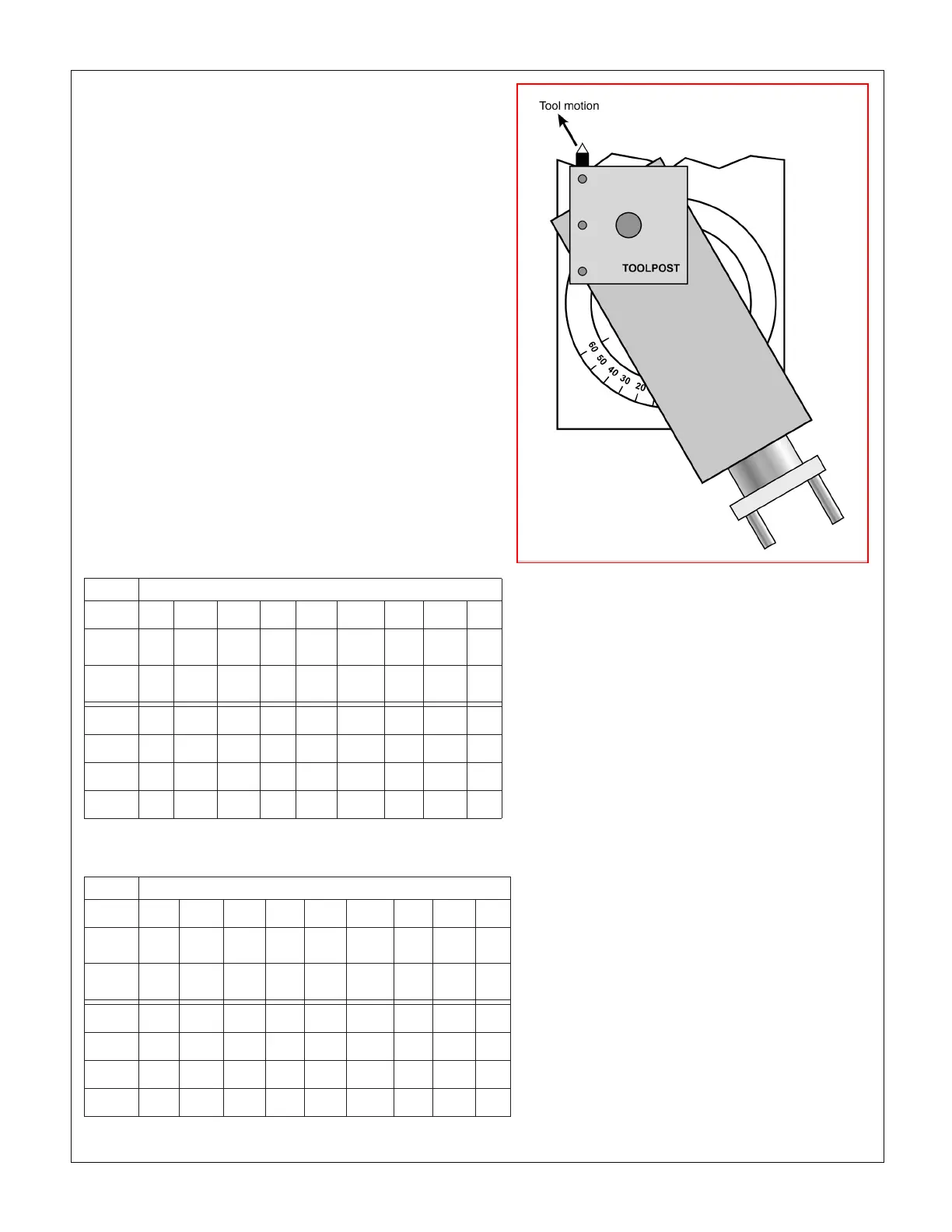
COMPOUND SETUP FOR THREAD CUTTING
Thread cutting on the lathe is unlike most other turning
operations, for two reasons: 1. The cutting tool must be
precisely ground with an included angle of 60 degrees
for most American and metric threads, and; 2. It is pref-
erable to feed the tool into the workpiece at an angle
so it cuts mostly on the left ank of the thread, Figure
3-11. The correct angle relative to the cross slide (zero
degrees) is debatable — should it be 29, 29-1/2 or 30
degrees? Many machinists prefer 29 degrees because
it holds the cutting tool marginally clear of the right ank
of the thread, close enough for cleanup of the ank while
at the same time avoiding appreciable rubbing.
CUTTING PROCEDURE FOR TPI THREADS
This procedure assumes that a single point thread cut-
ting tool will be used, and that the threading dial assem-
bly, Figure 3-13, has been pivoted forward to engage its
worm wheel with the leadscrew.
The threading dial cannot used for metric threads!
The split-nut on the apron must be left engaged
throughout the entire process.
For metric and UNC/UNF threads the tool is ground to
60
o
(included angle). It is installed so that its anks are
exactly 30
o
either side of the cross axis, ideally with the
compound oset as Figure 3-11. Single-point threads
are cut in 10 or more successive passes, each shaving
a little more material o the workpiece.
Figure 3-11 Setting up the compound for 30
o
infeed

 Loading...

