11
PM 25MV v9 2021-12 Copyright © 2021 Quality Machine Tools, LLC
QUILL DOWNFEED
The quill is controlled in two dierent ways, coarse and
ne.
In the drilling mode, coarse feed, the mill operates like a
standard drill press with a 3-lever hub; lever action low-
ers or raises the quill in the usual way by rack and pin-
ion. Return action is assisted by a compression spring
within the quill and spindle assembly.
For milling operations the lever hub is not rotated by le-
ver action. Instead it is locked to a worm wheel, which
is turned by the ne control knob. This allows the quill
to be driven precisely to any desired position. The ne
control knob, because it drives through a worm, cannot
be back-driven by return-spring action on the quill (in
other words, it stays where it’s put). For milling opera-
tions the quill should be locked by the lever on the left of
the headstock, Figure 3-1.
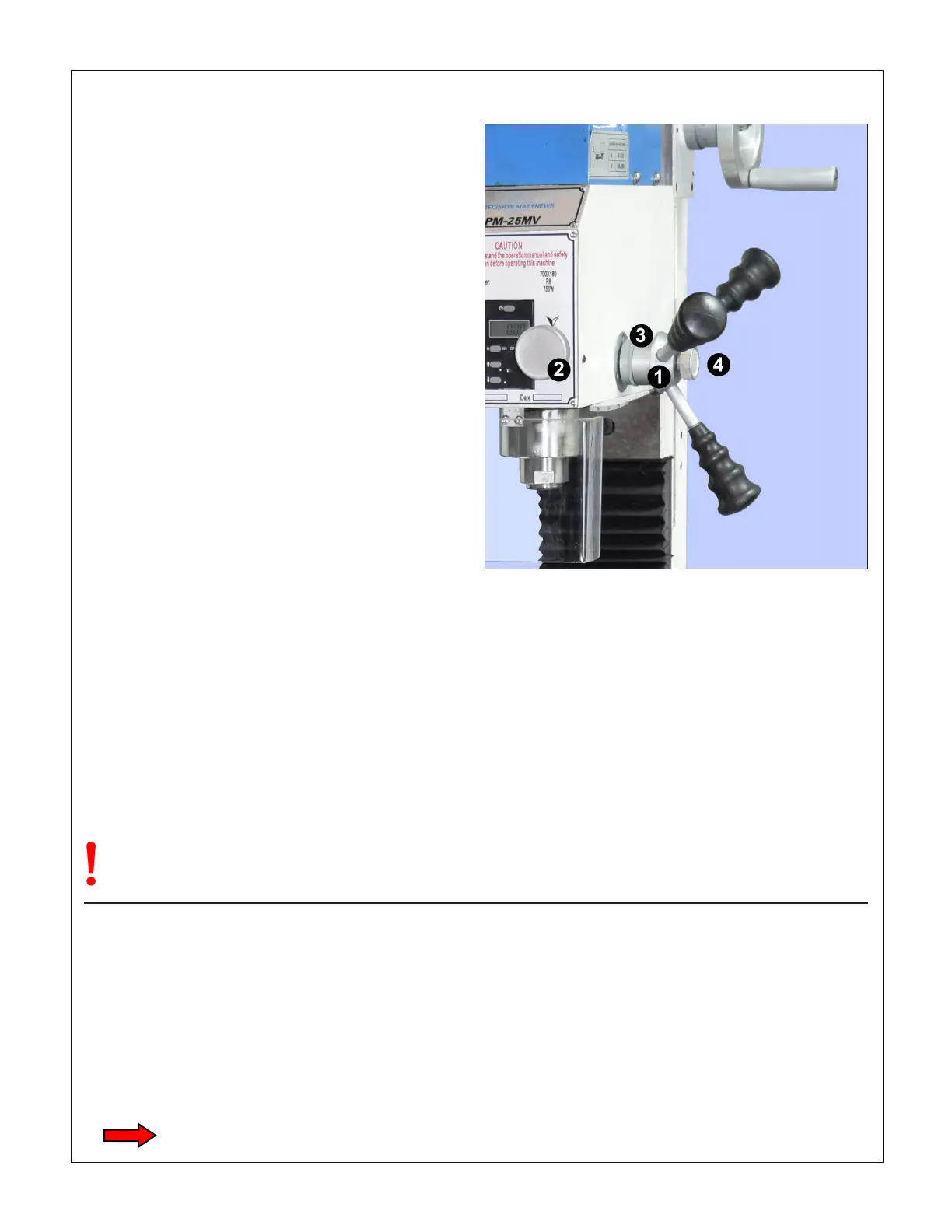
Coarse feed (Figure 3-7)
For drilling operations, loosen knob (4), allowing the le-
ver hub to rotate independently of sleeve (3).
Fine feed (Figure 3-7)
For milling operations calling for precise, repeatable
control of tool depth, tighten knob (4) to engage hub (1)
with the internal taper on sleeve (3). Tighten the Z-axis
locks, Figure 3-6.
Rotate the ne control knob (2) to raise or lower the quill.
Lower the quill by rotating the ne control knob clock-
wise, positioning it precisely either by counting divisions
on the graduated dial, or by reference to the digital read-
out (DRO), Figure 3-1. Use the locking lever left of the
headstock to hold the quill rmly in position.
Figure 3-7 Quill downfeed controls
The lever hub (1) is connected at all times to the quill pinion, which
engages a rack on the back side of the quill. The ne control knob
(2) drives sleeve (3) through a worm gear. If clamp knob (4) is
unscrewed, both (2) and (3) rotate freely, doing nothing to the quill.
Fine feed is engaged by tightening knob (4) to clamp (3) and (1)
together.
If you are counting downfeed divisions be
aware of backlash in the worm drive.
The quill DRO – which has no backlash issues – oers a
much less laborious way of setting tool height, but note
that the quill is spring-loaded. This calls for care when
releasing the quill locking lever. If the ne control knob
has been allowed to disengage (backed o counter
clockwise), the quill may jump up by 0.01” or more. To
avoid this, make sure the ne control has been turned
clockwise to apply downward pressure on the quill be-
fore the locking lever is released.
QUILL DRO
The quill DRO is in metric mode when switched on.
Press the mm/in button to display inches.
Replace the battery by removing the small molded cov-
er on the face of the DRO unit (align the dots). Check
the type number and voltage of the installed battery. Re-
place with an equivalent silver oxide cell available from
local retailers.
Switch o the DRO when not in use!

 Loading...