Do you have a question about the Precision matthews PM-25MV and is the answer not in the manual?
Troubleshooting guide for a mill that fails to operate, covering power, E-stop, and fuses.
Solution for R8 collets not fitting into the spindle, focusing on the locating screw.
Addresses issues with table movement towards the column, involving X-axis lock handles.
Explains correct drawbar installation procedure for proper spindle operation.
Step-by-step guide for unpacking and setting up the milling machine on a bench or stand.
Instructions for cleaning machining debris and applying rust preventative to the mill.
Pre-operation checks including chuck, speed control, power connection, and E-stop.
Steps for safely testing the machine's motor, speed control, and emergency stop functions.
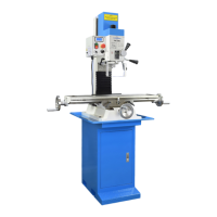
Overview of the PM-25MV mill's design, capabilities, and key features like spindle speed and DRO.
Detailed specifications including weight, dimensions, electrical requirements, headstock, spindle, and table details.
Essential safety tips for operating the milling machine, covering PPE, work area, and tool handling.
Explanation of the power, E-stop, chip guard, and spindle direction/speed controls.
Guide to adjusting belt for low and high speed ranges on the PM-25MV milling machine.
Procedures for installing and removing R8 taper collets, drill chucks, and other arbors.
Explains X and Y axis movement, handwheels, graduated dials, and leadscrew backlash.
Details on adjusting headstock height using the Z-axis crank and locking it in position.
Describes coarse and fine feed mechanisms for quill operation and tool depth control.
Information on using and maintaining the quill Digital Readout unit, including battery replacement.
Method for precise workpiece positioning using handwheel divisions, avoiding the quill lock.
Guidance on threading drilled holes, tap alignment, and power tapping considerations.
How to adjust headstock tilt for various angles and the importance of re-establishing vertical alignment.
Procedure for removing the headstock, noting potential set screws in addition to nuts.
Detailed procedure for aligning the spindle perpendicular to the table using a dial indicator and adjusting tilt.
Guide to installing and aligning a milling vise using a dial indicator for accuracy.
Explanation of using vise keys for quick and accurate vise removal and replacement.
List of recommended oils and greases for various machine components like leadscrews and bearings.
Importance of lubrication for preventing wear and guidelines for oiling moving parts.
Procedure for adjusting gibs on X, Y, and Z axes to ensure proper fit and smooth movement.
Methods for correcting excessive backlash in X and Y axis leadscrews by adjusting split nuts.
Information about the quill's automatic retraction and the return spring mechanism.
Guidance on servicing tapered roller bearings, including lubrication and avoiding over-packing.
Step-by-step instructions for removing and servicing the quill and spindle assembly.
Diagram illustrating the electrical connections and power flow for the milling machine.
Exploded view diagram of the milling machine's head assembly with numbered parts.
Detailed list of part numbers and descriptions for the milling machine's head components.
Exploded view diagram of the table, column, and base assemblies with numbered parts.
Detailed list of part numbers and descriptions for the table, column, and base assemblies.
Diagram and parts list for the chip guard assembly, including the switch box and shield.
| Motor Power | 1 HP |
|---|---|
| Spindle Taper | R8 |
| Max Speed | 2500 RPM |
| Drilling Capacity | 1/2" |
| Milling Capacity (Face) | 3" |
| Milling Capacity (End) | 1" |
| Number of Speeds | Variable |