Do you have a question about the Precision matthews PM-30MV and is the answer not in the manual?
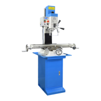
General introduction to the PM-30MV milling machine, detailing key specifications and capabilities.
Instructions for removing shipping protection and cleaning the machine.
Pre-operation checks to ensure the machine is ready and safe for use.
Steps to safely start and test the machine's motor and speed functions.
Overview of the PM-30MV milling machine's capabilities, design, and key physical dimensions.
Details on motor controls, E-stop, spindle direction, and speed selection/adjustment.
Procedures for installing tooling and operating the table's X and Y axes.
How to adjust the headstock height using the Z-axis crank and positioning.
Instructions for using quill downfeed controls and the Quill Digital Readout (DRO).
Techniques for edge finding, table positioning, and tapping operations.
Procedures for adjusting the headstock's tilt angle relative to the table.
Process for ensuring the spindle is perpendicular to the table for precision work.
Steps for installing, indicating, and using vise keys for accurate setup.
Recommended lubricants, general oiling, and gib adjustment procedures.
Correcting leadscrew backlash, quill return spring, and spindle bearing maintenance.
Procedures for removing the headstock and servicing quill/spindle assemblies.
Instructions for installing the optional X-axis power feed unit.
Electrical schematic, control box diagram, and parts list.
Exploded view and parts list for the chip guard assembly.
Exploded view of the headstock assembly with component references.
Exploded views and parts lists for the table and base assemblies.
Exploded view of the column assembly with component references.
| Brand | Precision matthews |
|---|---|
| Model | PM-30MV |
| Category | Power Tool |
| Language | English |