14
PM-30MV v3 2020-10 Copyright © 2020 Quality Machine Tools, LLC
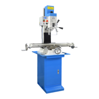
Figure 3-18 Indicating the vise
The tip of a standard dial indicator, arrowed, rides along the side face
of a ground reference bar (or the front face of the back jaw).
INSTALLING & INDICATING A VISE
For routine milling operations the workpiece is held in a preci-
sion vise. For the PM-30MV a 4” vise is most suitable. “Indicat-
ing” means checking the alignment of the xed (back) vise jaw
relative to the axis of table motion.
Tramming calls for patience! Expect to tighten and
re-check at least three times (simply tightening the
bolts can itself aect the tram).
Install the T-bolts and align the vise by eye. With one of the
clamp nuts snug, but not tight, tighten the other one just short
of fully-tight (but tight enough so the vise won’t budge without
a denite tap from a dead-blow mallet).
A typical setup for indicating is shown in Figure 3-18. Although
there is no spindle lock, you need to make sure that the spin-
dle does not rotate throughout the procedure. Set the indica-
tor tip against the upper edge of a precision reference bar or,
if not available, use the front face of the xed jaw of the vise
instead (check for dings, hone if necessary). Adjust the Y-axis
to pre-load the indicator to mid range at the tightly-clamped
side of the vise, then lock the Y-axis.
A procedure similar to the above may be used to check tram
in the Y-axis, front to back. The dierence here is that there
is that Y-axis tram is established in manufacture, and can be
adjusted only by these shop methods:
1. Shimming between the dovetailed Z-axis saddle casting
and the headstock itself. It is more likely that the head-
stock is nodding forward rather than leaning backward,
so start with (say) a 2 mil shim in line with the underside
(central) headstock nut. This is a temporary x that will
need to be checked if the headstock is tilted again.
2. Shimming between the underside of the column and the
main base casting. This is a long-term x. It is a two-per-
son procedure, requiring an engine hoist or some other
means of un-weighting the headstock (see Section 1, In-
stallation). As an alternative to shims, which do not pro-
vide a uniform bearing surface, consider injecting a met-
al-lled two-part polymer.
Note the indicator reading, then watch the indicator as you tra-
verse the table slowly toward the loosely clamped side. (Also
watch for any sign of spindle rotation.) Ideally, there should
be no discrepancy between the indicator readings at the two
ends — unlikely at the rst attempt. Return the table to the
starting point, then repeat the process, tapping the vise in as
you go. Repeat the process as often as necessary for the de-
sired accuracy, progressively tightening the “looser” nut. Now
fully tighten both nuts, and re-check again (tightening a nut
can itself introduce signicant error). An established routine
like this – tight to loose – can save a lot of time.
Most users aim for an end-to-end dierence of not more than
± 0.001” over the width of the vise jaw.
VISE KEYS
Most precision vises come with key slots on the underside ma-
chined exactly parallel to the xed jaw. Keys installed in the
slots can be a great time saver, Figure 3-19. Properly installed
they allow the vise to be removed and replaced routinely, ac-
curately enough for general machining without the need for
indicating every time.
Most 4” vises have either 14 mm or 16 mm slots, calling for
shop-made adapter keys as Figure 3-20. It is well worth the
eort to make these precisely. Aim for a snug t in both vise
and table, but not so tight that it takes more than reasonable
eort to lift the vise clear. Case hardening is recommended,
with nal tting using a ne stone or diamond stone.
Figure 3-20 Shop-made vise key
Dimensions in millimeters
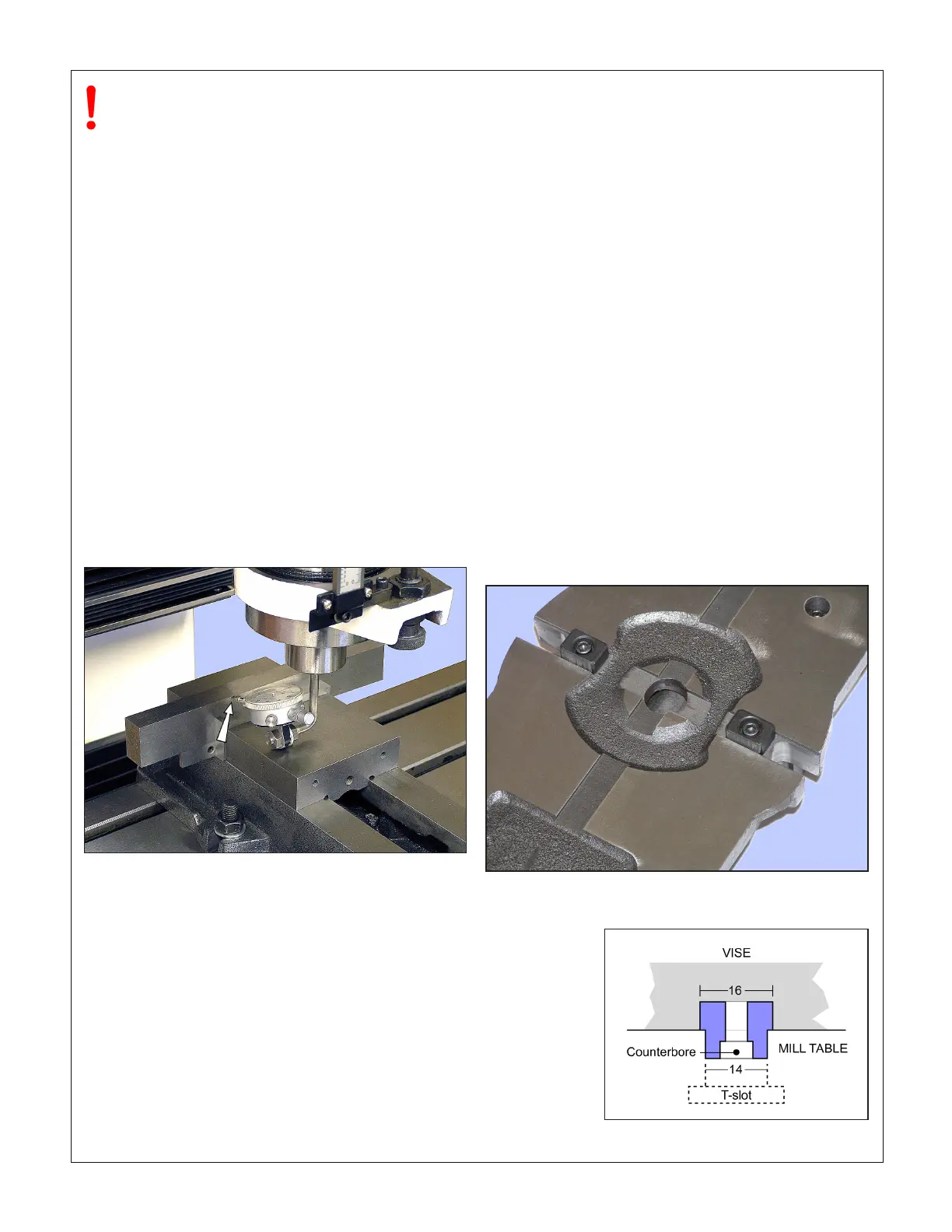
Figure 3-19 Vise keys installed on X-axis
On most vises the keys can also be installed on the long axis.
This vise came with 14 mm slots,
so the keys have parallel sides
 Loading...