PrecisionTemp
Cincinnati, Ohio
(513) 641-4446 Fax (513) 641-0733
www.precisiontemp.com
Rev 04/07
5
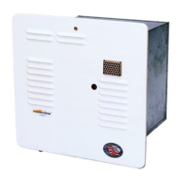
• Put the door onto the frame and adjust the frame so the door screw threads align with the
screw catch.
• Remove the door and tighten the top center screw
• Apply silicone or other appropriate sealant under the RV-500 flange. Push unit into open-
ing to bed into the sealant.
• Now screw in the other three center screws. Apply silicone or other appropriate sealant
heavily in the corners and completely around the flange. Remove excess sealant.
Connecting Gas Supply
The gas line should be of approved type and size with a 3/8" female flare nut. If the gas line
is very long or has numerous bends in it, it should not be less than 5/16" ID or performance of
the water heater will suffer. The maximum inlet gas pressure must not exceed 13 water col-
umn inches.
Some standards may require a manual gas shut off valve in the gas line external to the water
heater. The water heater must be isolated from the gas supply system during any pressure
testing of that system at test pressures equal to or in excess of 1/2 PSIG.
To Connect A Gas Line:
1. Remove foil insulation and set aside until gas line connection is complete.
NOTE:
The gas line can be routed into the case through the grommet in the back or through
the side of the case. If the gas line is to be brought into the side of the case, the positions of
the knockout plug in the side of the case and the sealing grommet in the back of the case
should be reversed. Both of these devices will snap in and out.
Never operate heater with either of these holes left open. The gas inlet fitting on the top of
the gas solenoid valve must be repositioned to point to the side of the case. To do so, sup-
port the gas valve and back-up with a wrench, turn the gas fitting 1/4 turn clock-wise taking
care not to damage the threads. Caution: Turning the gas-fitting counter clock-wise may
cause the seal to leak.
2. Route gas line through sealing grommet (back or side) of heater case. Take care not to
damage wiring.
3. Screw gas line fitting onto the flare fitting of the gas valve by hand and then tighten with a
basin wrench or crow's foot.
4. Turn on gas supply and check for leaks using a soapy solution on the joint. Never use a
flame to check for leaks. Be sure that sealing grommet is intact. If it became torn or dis-
torted through the installation, fill cup on back of grommet with silicone caulk (RTV) to seal
against any possible leaks.
Warning: This flare fitting is a dry seal. Pipe dope should never be used on this fitting.
5. Replace the foil insulation taking care that it is secured to the Velcro attachment points.