EasyManua.ls Logo

Precor 9.45 User Manual

Precor 9.45
58 pages
To Next Page IconTo Next Page
Page #1 background imageLoading...
Page #1 background image
9.45, 9.45i Treadmill
Page 1
9.45, 9.45i Treadmill
Warning: This service manual is for use by Precor trained service providers only.
If you are not a Precor Trained Servicer, you must not attempt to service any Precor Product;
Call your dealer for service.
This document contains information required to perform the majority of troubleshooting, and
replacement procedures required to repair and maintain this product.
This document contains general product information, software diagnostic procedures (when
available), preventative maintenance procedures, inspection and adjustment procedures,
troubleshooting procedures, replacement procedures and electrical block and wiring diagrams.
To move directly to a procedure, click the appropriate procedure in the bookmark section to the
left of this page. You may “drag” the separator bar between this page and the bookmark section
to change the size of the page being viewed.
© 2003 Precor Incorporated
Unauthorized Reproduction and Distribution Prohibited By Law
Question and Answer IconNeed help?

Do you have a question about the Precor 9.45 and is the answer not in the manual?

Precor 9.45 Specifications

General IconGeneral
BrandPrecor
Model9.45
CategoryTreadmill
LanguageEnglish

Summary

Manual Introduction and Safety Warning

Service Provider Authorization

Warns that the manual is for trained service providers only.

Manual Scope and Purpose

Outlines the document's content for troubleshooting and maintenance.

Section One: Things You Should Know

Treadmill Model Versions

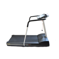
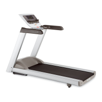
Describes treadmill design versions and serial number prefixes.

Section One: General Info & Specs

Provides general information and technical specifications.

Section Two: Software Features

Details diagnostic and setup features for the treadmill.

Section Three: Checking Treadmill Operation

Outlines procedures for verifying treadmill operation.

Section Four: Inspection & Adjustment

Covers inspection, adjustment, and maintenance procedures.

Section Five: Troubleshooting Procedures

Guides on isolating and diagnosing specific components.

Section Six: Replacement Procedures

Step-by-step guide for component removal and replacement.

Section Seven: Wiring and Block Diagrams

Provides electrical wiring and block diagrams for all versions.

Precor Dealer Website Information

Directs users to the Precor dealer website for parts.

Technical Specifications

Physical Specifications Overview

Details treadmill dimensions, weight, motor, speed, incline, and power.

Smart Rate System Description

Heart Rate System Functionality

Explains the heart rate system and its LED indicators.

Procedure 2.1: Accessing M9.45 Diagnostic Program

Diagnostic Program Routines

Lists the six diagnostic routines available for testing.

Procedure 2.2: Accessing M9.45i Diagnostic Program

Diagnostic Program Routines

Details the six diagnostic routines for the M9.45i.

Procedure 2.3: Resetting All User Information

User Information Reset Steps

Outlines the steps to reset all user statistics and odometer readings.

Procedure 2.4: Resetting Individual User Information

Individual User Reset Steps

Describes how to reset accumulated data for a specific User ID.

Procedure 2.5: Odometer and Error Log Display

Accessing Odometer and Error Data

Details how to view the treadmill's odometer reading and error log.

Procedure 2.6: Selecting Measurement Units

Checking Current Units

Verifies the treadmill's current measurement standard (US or Metric).

Changing Measurement Standard

Provides steps to switch between US and Metric units.

Procedure 2.7: Determining Software Version Numbers

Finding Software Version

Explains how to find and note the software version number.

Procedure 2.8: Documenting Software Problems

Information to Record for Software Issues

Details information needed when software problems occur.

Section Three: Checking Treadmill Operation

Treadmill Operation Check Procedure

Steps for performing a quick check of the treadmill's operation.

Procedure 4.1: Calibrating Lift Limit Switches (1L)

Side Rail Measurement for Calibration

Details measurement of side rail for calibration.

Procedure 4.2: Calibrating Lift Motor (2P/3Y)

Lift Motor Calibration Steps

Step-by-step instructions for calibrating the lift motor.

Procedure 5.1: Troubleshooting Keypad & Upper PCA

Keypad and Upper PCA Diagnosis

Troubleshooting steps for unresponsive console keys or PCA.

Procedure 5.2: Troubleshooting Heart Rate System

Heart Rate System Diagnosis

Steps to diagnose issues with the heart rate receiver or chest strap.

Procedure 5.3: Troubleshooting Lift System (1L)

Lift System Description and Diagnosis

Explains the lift system and provides troubleshooting steps.

Procedure 5.4: Troubleshooting Lift System (2P/3Y)

Lift System Overview and Troubleshooting

Describes the lift system and troubleshooting methods for 2P/3Y units.

Procedure 5.5: Troubleshooting AC Power Source

Dedicated 20 Amp Circuit Requirement

Stresses the need for a dedicated 20 amp AC circuit for operation.

120 Vac System Considerations

Specific details for troubleshooting 120 Vac power systems.

240 Vac System Considerations

Specific details for troubleshooting 240 Vac power systems.

Procedure 6.1: Replacing the SCR (1L Units)

Removing the SCR Component

Steps and diagrams for removing the SCR.

Replacing the SCR Component

Steps and guidelines for installing a new SCR.

Procedure 6.2: Replacing the Terminal Block (1L Units)

Removing the Terminal Block

Steps for removing the terminal block.

Procedure 6.3: Replacing Lift Motor, Sensor, or Magnet Hub (1L)

Removing the Lift Motor Assembly

Steps to remove the lift motor, rotation sensor, or magnet hub.

Replacing the Magnet Component

Instructions for removing and installing the magnet.

Replacing Rotation Sensor Bracket

Steps to remove and reinstall the rotation sensor bracket.

Replacing the Lift Motor Component

Steps for mounting the lift motor.

Procedure 6.4: Replacing Limit Switches, Actuator, or Bracket (1L)

Removing Limit Switches

Steps for removing upper, lower, and zero sense limit switches.

Removing Actuator Shaft and Switch Actuator

Steps to remove the actuator shaft and switch actuator.

Replacing Switch Bracket

Steps for removing and installing the switch bracket.

Replacing Actuator Shaft and Switch Actuator

Instructions for replacing actuator shaft and switch actuator.

Replacing Upper Lift Limit Switch

Steps for replacing the upper lift limit switch.

Replacing Lower Lift Limit Switch

Steps for replacing the lower lift limit switch.

Replacing Zero Sense Switch

Steps for replacing the zero sense switch.

Procedure 6.5: Replacing Lift Motor Capacitor (1L)

Removing Lift Motor Capacitor

Steps to remove the lift motor capacitor.

Replacing Lift Motor Capacitor

Steps to install the lift motor capacitor.

Procedure 6.6: Replacing the Transformer (1L Units)

Removing the Transformer Component

Steps for removing the transformer.

Procedure 6.7: Replacing Speed Sensor (1L Units)

Removing the Speed Sensor

Steps for removing the speed sensor.

Procedure 6.8: Replacing Speed Sensor (2P & 3Y Units)

Removing the Speed Sensor

Steps for removing the speed sensor.

Procedure 6.9: Replacing the Lift Platform

Removing the Lift Platform

Steps to remove the lift platform.

Replacing the Lift Platform

Steps to install the lift platform.

Procedure 6.10: Replacing Target Label (2P & 3Y)

Removing the Target Label

Steps to remove the target label from the flywheel.

Procedure 6.11: Replacing Lift Motor (2P & 3Y Units)

Removing the Lift Motor

Steps to remove the lift motor.

Procedure 6.12: Replacing the PROM

PROM Replacement Safety Precautions

Emphasizes anti-static precautions for PROM replacement.

Wiring Diagrams

Wiring Diagram 7.1: 9.45 1L Unit

Electrical connections for the 1L unit.

Wiring Diagram 7.3: 9.45 2P & 3Y Units

Electrical connections for 2P & 3Y units.

Block Diagrams

Block Diagram 7.2: 9.45 1L Units

Functional block diagram for 1L units.

Block Diagram 7.4: 9.45 2P & 3Y Units

Functional block diagram for 2P & 3Y units.

Related product manuals