Thank you for choosing Precor. For proper installation, please read this guide
thoroughly and follow the assembly instructions. If you do not assemble the
treadmill according to these guidelines, you could void the Precor Limited Warranty.
Important (240 volt 9.27 model only): If the power cord attached to
your equipment is not compatible with your local power plug standards,
the container should also include a power cord for your region. You will
need to install this cord in place of the one attached to the equipment.
If you need such a cord and it was not included with your treadmill,
please contact your Precor dealer for the correct Precor power cord.
For a list of authorized Precor dealers in your area,
please contact Customer Support at www.precor.com.
Obtaining Service
Do not service the treadmill except for minor belt
adjustments and maintenance tasks as described in the
owner’s manual. For more information regarding customer
support numbers or a list of Precor authorized service
dealers, visit the Precor web site at www.precor.com.
Unpacking the Equipment
The unit is shipped in one box. Ask for help from two
or more people to unpack and assemble the treadmill.
If any items are missing, contact your dealer.
Required Tools
Phillips-head screwdriver
Crescent wrench
Level
Wire cutter
Installation Requirements
CAUTION: You will need assistance to
assemble this unit. DO NOT attempt
assembly by yourself.
Follow these installation requirements when
assembling the unit:
Assemble the unit near the location
where you plan to use it and provide
ample space around the unit.
Important: Consult your owner’s
manual for proper placement of
your equipment.
Make sure that the power switch
is OFF and that the treadmill is not
plugged into a power source.
Check the ON/OFF power switch on the
front of the treadmill. Place the switch
in the O (OFF) position.
Assemble unit on a solid, flat surface.
Assemble the treadmill in the
sequence presented in this guide.
If you plan to move the unit, obtain
help and use proper lifting techniques.
Grasp the rear end of the treadmill or either
side of the running belt. Lift the treadmill and
roll it on its front wheels. Do not grasp any other
plastic part while lifting or moving the unit. The
other plastic parts are not reinforced and they
may break.
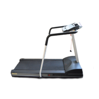
9.23 / 9.27
Have your assistant lower the handrail assembly onto the upright supports. Tip the assembly
slightly forward so the lip of each handrail cap rests on the upright support. Align the mounting
holes and insert six buttonhead screws (A) and six washers (B). Finger tighten.
Important: Make sure the fasteners do not pinch the cable. Cables damaged by improper
installation will not be covered by the Precor Limited Warranty.
Note: To attach the handrails to the 9.27, perform step 7 installing one handrail at a time.
If you have a 9.23, skip to step 8.
Attach the handrails (9.27 model only)
a. Attach the base of the handrail to an upright support using one long buttonhead screw (F).
Insert the long buttonhead screw through the upright support, and then slide the handrail
stub into the center handrail while you thread the long screw into the base of the handrail.
CAUTION: Use your fingers to properly align and thread the long screw into the
mounting hole. This will help avoid cross-threading.
b. Insert two buttonhead screws (D) to secure each handrail stub to the center handrail.
Wrench tighten all the handrail screws with a 4 mm hex key.
Tighten all mounting screws. Refer to the illustrations for steps 2
through 7.
a. Start at the base and use the 5 mm hex key to alternately tighten
the 4 front panel screws.
b. Use the 6 mm T-handle hex key to wrench tighten the 4 socket head
side bracket screws.
c. Use the 5 mm hex key to wrench tighten the six screws that secure
the handrail extensions to the upright supports.
Attach the left upright support following the
procedures in steps 2 and 3, using two buttonhead
screws (A), two socket head screws (C), and four
washers (B). Finger tighten.
CAUTION: The On/Off switch is located beneath the hood on the base frame.
Make sure the power switch is in the Off position and the power cord is
disconnected from its power source.
Unwind the wire tie from the base of the right upright support and feed it
through the large hole. Unwrap the cable and secure it to the wire tie. Pull
the wire tie and cable through the upright support as you position it against
the base frame side bracket.
Ask your assistant to insert a buttonhead screw (A) and washer (B) into
the top mounting hole on the front panel. Thread the screw so the other
mounting holes line up. Then insert a buttonhead screw (A) and washer (B)
in the bottom mounting hole. Finger tighten.
Note: Do not force the fasteners into place and do not tighten them
completely until instructed to do so. If the head of the fastener is not
flush with the head of the product, contact Customer Support
at www.precor.com.
Secure the upright support to the base frame side bracket using
two socket head screws (C) and washers (B). Place each screw
on the 6mm T-handle hex key and insert it through the cutout in the
upright support. Wrench tighten so the upright is stable, but leave
room for adjustments.
Ask your assistant to hold the handrail assembly while
you connect the cable. Remove the wire tie and place
any excess cable inside the upright support.
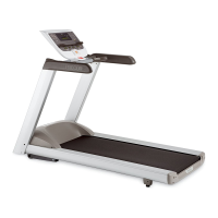
Note: The 9.27 handrail assembly shown here is slightly
different from the 9.23 treadmill. If you are assembling a 9.23,
you will not have mounts for the side handrails.
Install the display console.
a. Remove the display console from its box and protective packaging.
b. Cut any wire ties that secure the cables to the center handrail.
c. Ask your assistant to hold the display console above its mounting
bracket while you connect the cables to their appropriate
receptacles on the back of the display console. Tabs exist on
each connector so you can align it properly.
d. Secure the cables under the clips in the indented area on the back
of the display console and lower the display console onto its
bracket.
e. Feed any excess cable into the center handrail.
f. Align the four mounting holes and secure the display console with
four buttonhead screws (D) and four washers (E). Wrench tighten
using a 4 mm hex key.
Slide the two water bottle holders onto their brackets and secure each with a
buttonhead screw (G) and washer (H). Tighten each screw with a Phillips-head
screwdriver.
Note: In the 9.27 packaging, you will find a chest strap. Refer to the QUICKSTART
card to learn how to use it. If you are interested in purchasing a chest strap for the
9.23, refer to Obtaining Service.